
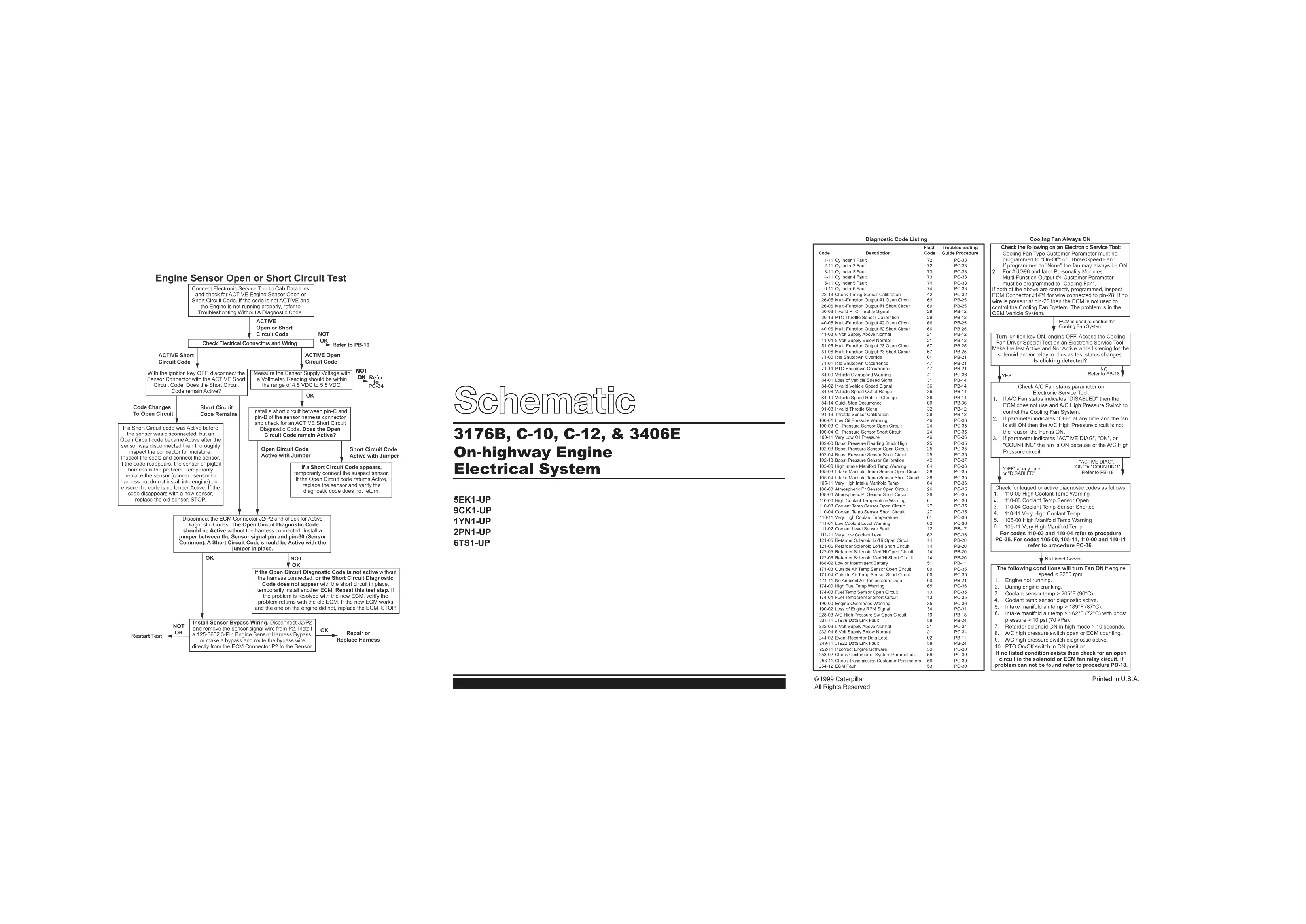
This Caterpillar 3406E electrical schematic is the cover and diagnostic code index for the 3176B, C-10, C-12 and 3406E on-highway engine electrical system. It lists diagnostic codes with their flash codes and the troubleshooting procedure to follow for each fault.
Official document details
| Brand | Caterpillar (CAT) |
|---|---|
| Engine coverage | 3176B, C-10, C-12, 3406E on-highway engine |
| Serial ranges | 5EK, 9CK, 1YN, 2PN, 6TS |
| System / Group | Electrical system schematics |
| Copyright | 1999 Caterpillar |
| Pages | 1 |
| File size | 50 KB |
| Format / Language | PDF / English |
Caterpillar 3406E electrical schematic table of contents
- Diagnostic code listing with flash codes
- Cooling fan system diagnostic sequence
- Engine sensor open or short circuit test
- ECM connector J1/P1 and J2/P2 references
- Coolant, boost, oil pressure and manifold temperature codes
- Multi-function output circuit codes
- J1939 and J1922 data link fault codes
Applicable truck models covered
The schematic set applies to Caterpillar 3176B, C-10, C-12 and 3406E on-highway engines within the 5EK, 9CK, 1YN, 2PN and 6TS serial ranges. This cover page indexes the codes; the accompanying wiring schematic sheet shows the physical circuits and connector pins. See the manufacturer at Caterpillar.
Who needs the Caterpillar 3406E electrical schematic
Diesel technicians reading Cat ET fault data use this 3406E electrical schematic because it converts each diagnostic code, such as 110-03 coolant temp sensor open, into a flash code and a specific PB or PC troubleshooting procedure number.
A flash code lets a driver read a fault by counting lamp blinks when no electronic service tool is at hand, and this index pairs every listed condition with the procedure that resolves it. The cooling fan diagnostic explains why a fan may run continuously, pointing to the cooling fan type customer parameter, the A/C high pressure circuit, or an open in the solenoid or relay when no listed condition is present. The engine sensor open or short circuit test walks through disconnecting the ECM J2/P2 connector, installing a jumper and confirming whether the code follows the harness, the sensor or the module, so a good part is never replaced by mistake.
The full PDF is available in the DiagTechPro manuals library; a free account is required to download it.
Related manuals library
Sản phẩm liên quan cho hãng này
Cùng brand theo taxonomy hiện có trong catalog WooCommerce.

CAT Perkins Pack – Premium Power & Performance by Caterpillar

CAT SIS


