
This DuraStar HVAC service manual (publication S16025, 2005) is the factory heat, ventilation and air conditioning section for International DuraStar trucks. It documents system operation, every major component and the A/C performance test.
Official document details
| Brand | International Trucks (Navistar) |
| Model coverage | International DuraStar (4000 Series) |
| System / Group | HVAC |
| Publication no. | S16025 |
| Year / Revision | 2005 |
| Pages | 246 |
| File size | 3.4 MB |
| Format | |
| Language | English |
What the DuraStar HVAC service manual covers
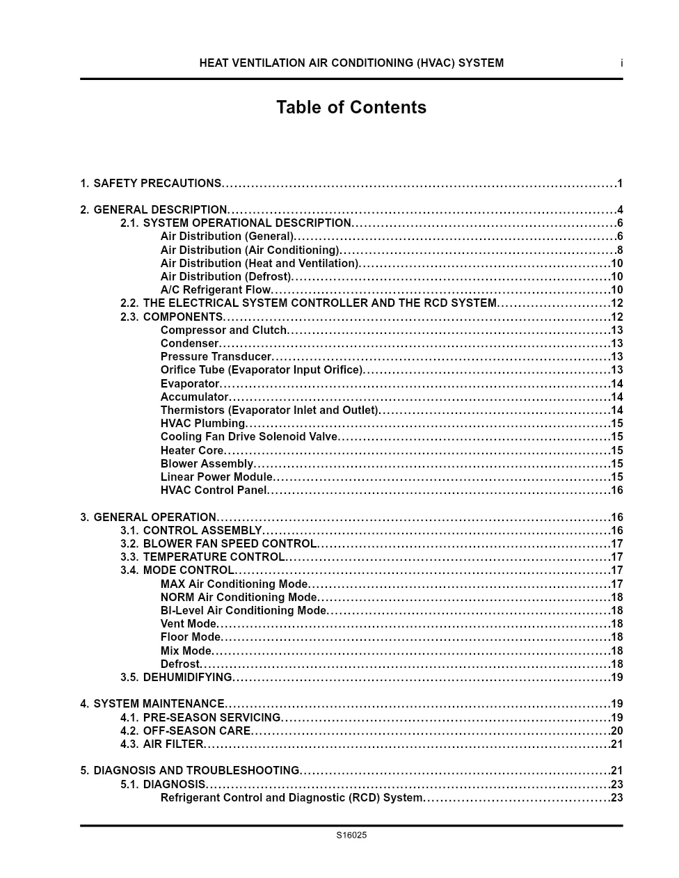
- Safety precautions and general description
- System operational description and air distribution
- A/C refrigerant flow
- Electrical System Controller and RCD system
- Components — compressor, condenser, evaporator, accumulator
- Orifice tube, thermistors and heater core
- Control assembly, blower, temperature and mode control
- System maintenance and A/C performance test
Publication S16025 describes the orifice tube air conditioning circuit, the Electrical System Controller and RCD system, and a system-pressure-versus-ambient-temperature chart for R134A. It includes the A/C performance test and recirculation-motor circuit troubleshooting.
Applicable truck models
This HVAC section covers International DuraStar (4000 Series) trucks. Verify your control head and refrigerant charge before testing. Learn more at the International Trucks official website.
Who needs this DuraStar HVAC service manual
A/C specialists and fleet shops use this section to diagnose weak cooling, replace evaporators and compressors and confirm charge against the pressure chart. It is written for trained professionals.
Diagnosis leans on the pressure-versus-temperature chart and the A/C performance test: record duct temperatures, thermistor values and transducer readings, then compare them before replacing parts. The orifice-tube system depends on a clean, properly evacuated circuit, so flush when required and add refrigerant oil only per the oil-fill guidelines. Recirculation-motor and control-head faults are traced through the Electrical System Controller using the troubleshooting charts. If a thermistor reads more than a few degrees off its partner, or the transducer differs from the gauge set by more than twenty psig, the section points you to the exact circuit to check before condemning the compressor or control head.
The full PDF is available in the DiagTechPro manuals library — a free account is required to download. Each listing shows the exact publication number so you can match the document to your VIN and build date before downloading.
Related manuals library

Sản phẩm phổ biến từ DiagTechPro
Gợi ý chung: các sản phẩm phổ biến của shop, không phải sản phẩm được gán cho hãng của tài liệu này.

Full Diesel Laptop Pack – All-in-One Diagnostic Solution for Diesel Technicians
ALLISON TCM REFLASH

ALLISON DOC


