
Cummins ISM Code 242 documents the Vehicle Speed Sensor Circuit Erratic diagnostic and troubleshooting procedure for the Cummins ISM CM570 (1999-02) engine platform. This 8-page fault code sheet from TruckFaultCodes.com (Copyright 2017) covers fault code 242 (PID P084, SPN 84, FMI 10/10, YELLOW lamp) and the checks used to confirm and clear it.
Official document details
| Brand | Cummins |
|---|---|
| Model coverage | ISM CM570, ISX CM570, Signature CM570 (1999-02) |
| System / Group | Diagnostic Trouble Codes (DTCs) |
| Fault code | 242 — PID P084, SPN 84, FMI 10/10 |
| Warning lamp | YELLOW |
| Pages | 8 |
| File size | 0.3 MB |
| Format | |
| Language | English |
Document table of contents
- Circuit description
- Component location
- Shop talk
- Troubleshooting steps
- Fault code verification and clearing
Cummins ISM Code 242 diagnostic steps
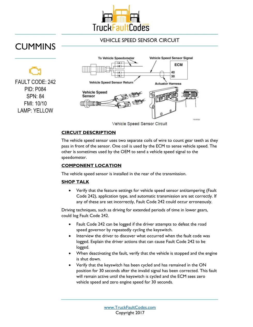
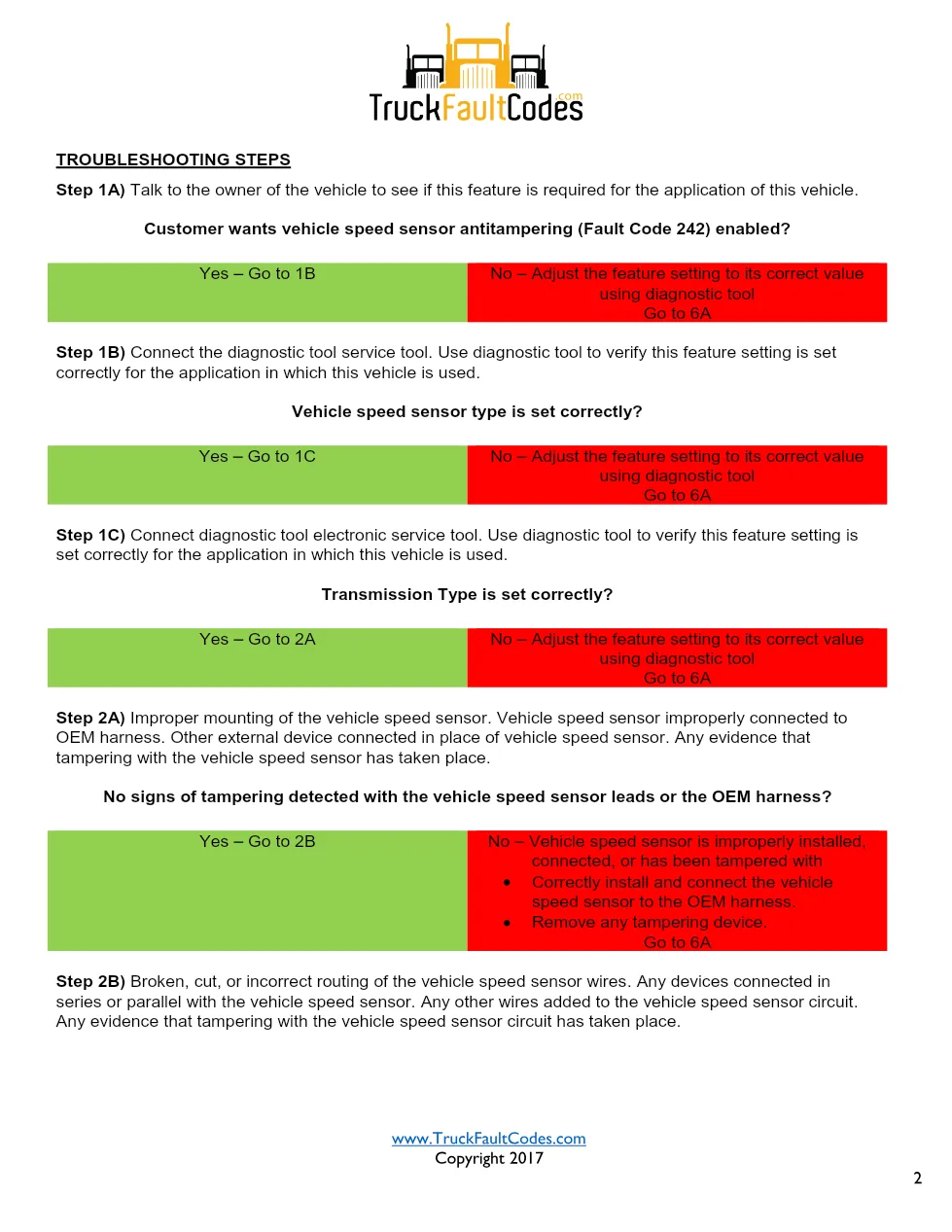
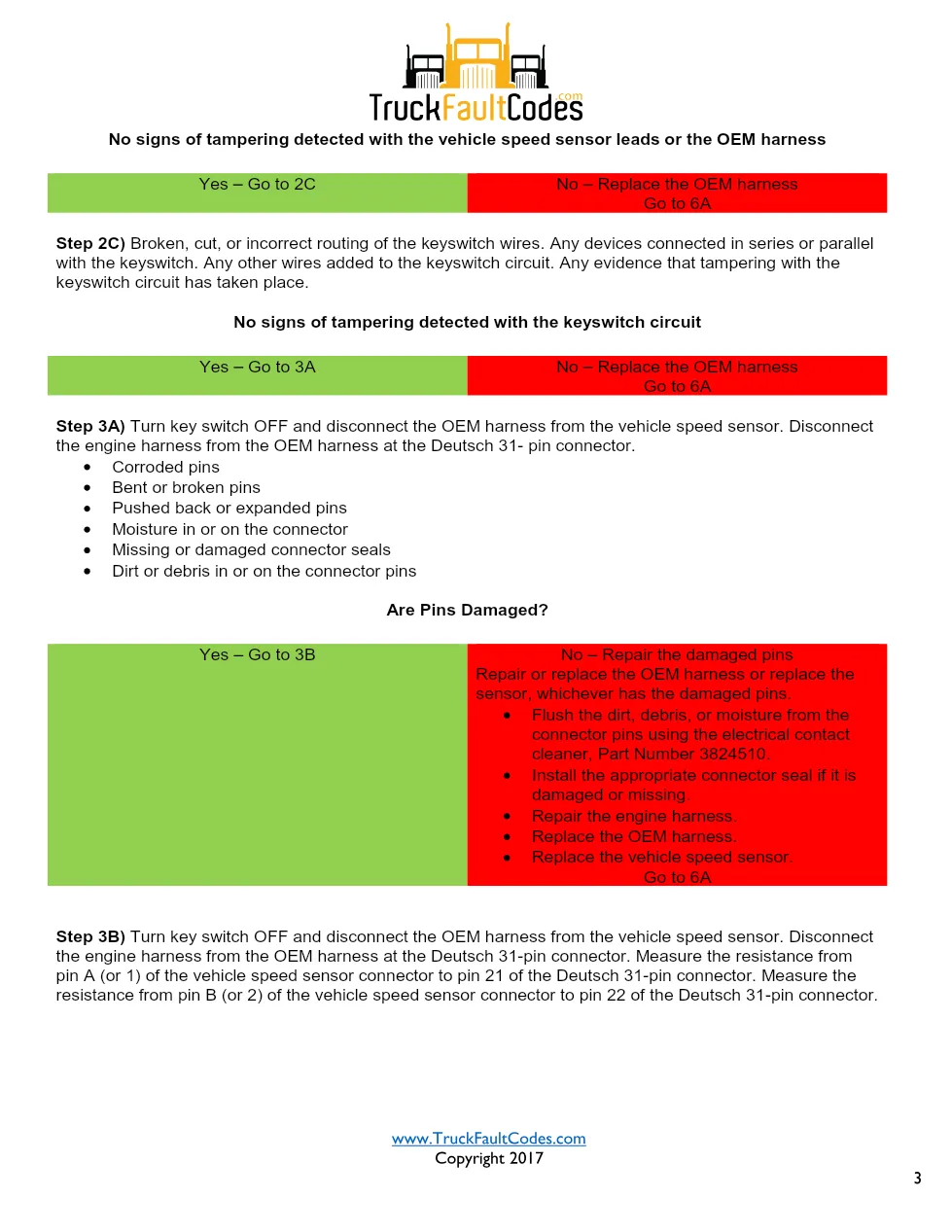
The vehicle speed sensor uses two coils to count gear teeth at the rear of the transmission. Because anti-tampering logic can log this fault, technicians first verify the feature settings for vehicle speed sensor anti-tampering, application type, and automatic transmission, and interview the driver about the event. The eight-page procedure then checks sensor wiring, twisted-pair integrity, and signal continuity before the fault is disabled and cleared with the diagnostic tool.
Applicable truck models
This sheet applies to Cummins ISM CM570, ISX CM570, and Signature CM570 (1999-02) engines built around the CM570 ECM and the vehicle speed sensor. The vehicle speed sensor is installed in the rear of the transmission. The document is laid out with a circuit description, a component location note, shop-talk tips, and a step-by-step troubleshooting chart whose go-to branches route the technician through each measurement. Refer to the official Cummins engine support site for wiring diagrams and component part numbers.
Who needs this Cummins ISM Code 242 manual
Heavy-duty diesel technicians, fleet service teams, and owner-operators diagnosing a yellow-lamp vehicle speed sensor fault will use this sheet to follow the factory decision tree, confirm the reading, and repair the harness, connector, or component instead of replacing parts on guesswork. It spells out each measurement threshold and its pass or fail branch, so the fault can be verified active, the repair validated, and the inactive code cleared with the diagnostic tool.
The full PDF is available in the DiagTechPro manuals library; a free account is required to download.
Related manuals library
Sản phẩm liên quan cho hãng này
Cùng brand theo taxonomy hiện có trong catalog WooCommerce.

Cummins INSITE 9.3 – The Essential Diagnostic Tool for Cummins Engines

Cummins Calterm Version 5.16 – Advanced ECM Control and Precision Tuning for Cummins Engines

Cummins InCal CE – The Calibration and Configuration Tool for Cummins Engines


