
This document is a Cummins 489 fault troubleshooting manual for the ISB CM550 auxiliary speed or auxiliary pressure input error. It explains the meaning of Fault Code 489, PID P191, SPN 191, FMI 0, and gives step-by-step checks for OEM auxiliary speed or pressure circuits. The procedure is written for technicians using a diagnostic tool, resistance measurements, voltage checks, and connector inspections.
Official Cummins 489 fault document details
| Brand | Cummins |
|---|---|
| Model coverage | ISB CM550 (1990-94) |
| System/Group | DTCs; auxiliary speed or auxiliary pressure input circuit |
| Year/Revision | Unknown; copywrite 2017 shown in file |
| Pages | 6 |
| File size | 0.4 MB |
| Format | |
| Language | English |
Document table of contents
- FAULT CODE: 489
- PID: P191
- SPN: 191
- FMI: 0
- AUXILIARY SPEED OR AUXILIARY PRESSURE INPUT ERROR
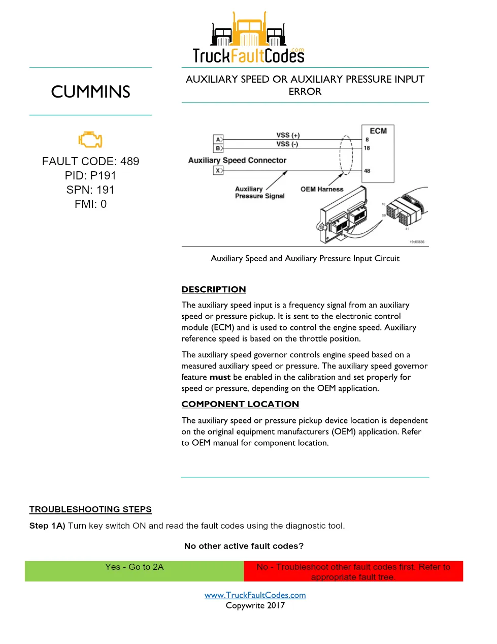
- Auxiliary Speed and Auxiliary Pressure Input Circuit
- DESCRIPTION
- COMPONENT LOCATION
- TROUBLESHOOTING STEPS
- Step 1A) Turn key switch ON and read the fault codes using the diagnostic tool.
- Step 2A) Refer to the OEM troubleshooting and repair manual.
- Step 3A through Step 3E auxiliary speed sensor checks
- Step 4A and Step 4B auxiliary pressure sensor checks
- Step 5A through Step 5D OEM harness and ECM connector checks
- Step 6A and Step 6B fault code disable and clear procedure
Applicable truck models
This file applies to Cummins ISB CM550 (1990-94) coverage where the OEM application uses an auxiliary speed pickup or auxiliary pressure pickup connected to the ECM. The document states that component location depends on the original equipment manufacturer application, so the OEM manual is required for the exact device location and equipment function checks. See the manufacturer at Cummins official website.
Who needs this Cummins 489 fault manual
This Cummins 489 fault manual is for diesel mechanics, fleet workshops, and service managers diagnosing an active or inactive auxiliary speed or auxiliary pressure input error on ISB CM550 equipment. It is useful when checking slipping clutches, broken driveline components, OEM pressure, sensor adjustment, sensor resistance, shorts to ground, open circuits, and pin-to-pin shorts.
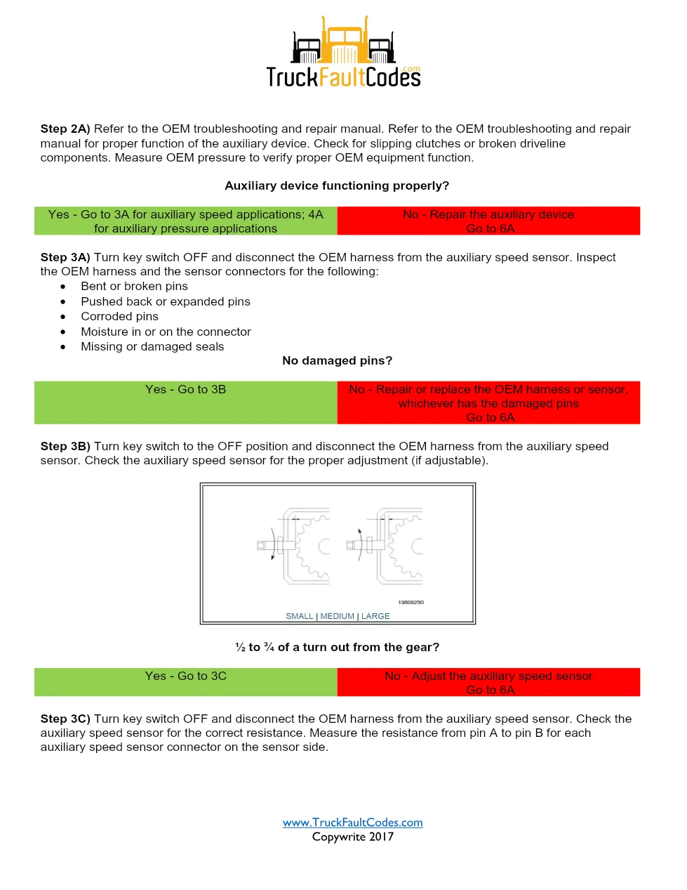
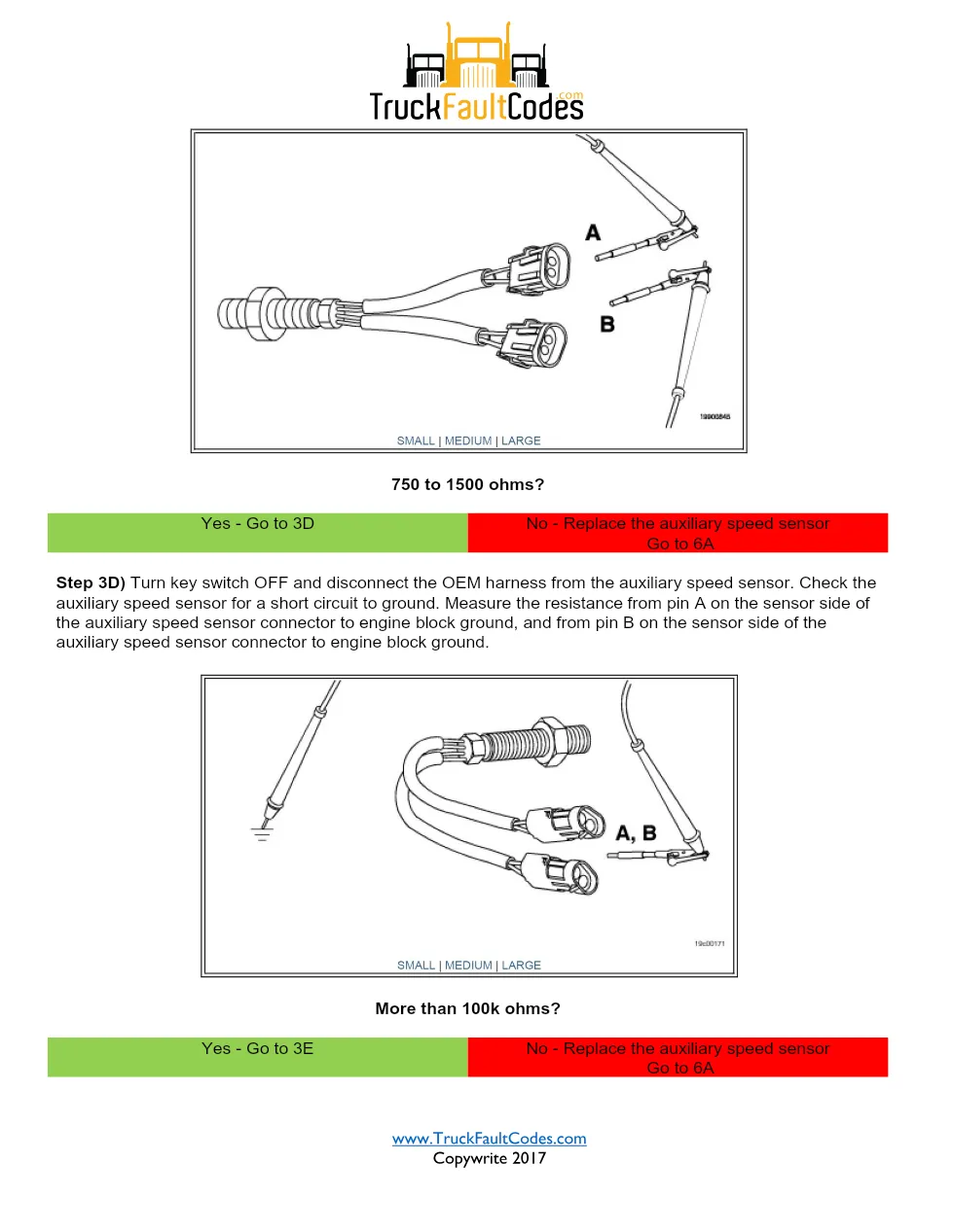
The diagnostic sequence starts by reading active fault codes and repairing other faults first if present. It then separates auxiliary speed applications from auxiliary pressure applications, inspects pins and seals, checks the speed sensor adjustment at ½ to ¾ of a turn out from the gear, verifies 750 to 1500 ohms sensor resistance, checks for more than 100k ohms to ground, and confirms pressure sensor voltage at pin 48 is (+) 0.5 to 4.5 VDC. Harness checks include pins 8, 18, and 48, with less than 10 ohms for continuity and more than 100k ohms for short-circuit tests.
Full PDF available in the DiagTechPro manuals library, free account required to download.
Related manuals library
Sản phẩm liên quan cho hãng này
Cùng brand theo taxonomy hiện có trong catalog WooCommerce.

Cummins Calterm Version 5.16 – Advanced ECM Control and Precision Tuning for Cummins Engines

Cummins INSITE 9.3 – The Essential Diagnostic Tool for Cummins Engines

Cummins InCal CE – The Calibration and Configuration Tool for Cummins Engines


