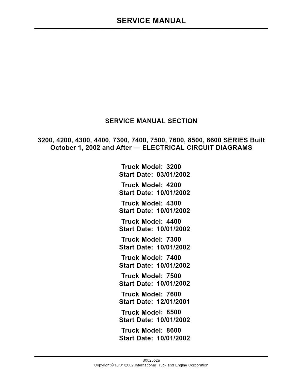
The 3200 wiring diagrams (publication S082852a) are International’s electrical circuit diagrams for the 3200 and related medium- and heavy-duty trucks built October 1, 2002 and after. This 187-page manual provides 12-volt power distribution, data link, and accessory circuit diagrams together with connector composites and pinouts. Diagrams are drawn as a restricted-basis print by International Truck and Engine Corporation.
3200 wiring diagrams document details
| Brand | International Trucks |
| Model coverage | 3200, 4200, 4300, 4400, 7300, 7400, 7500, 7600, 8500, 8600 Series |
| System / Group | 3000 Series / Wiring Diagrams |
| Publication no. | S082852a |
| Year / Revision | Built October 1, 2002 and after |
| Pages | 187 |
| File size | 3.3 MB |
| Format | |
| Language | English |
Document table of contents
- Instructions and charts: circuit number identification and location
- Schematic symbol chart, relay functions and lamp bulb chart
- NAVPAK/ECM engine controller connector pin identification
- 12-volt power distribution: accessory, battery feeds, 1708 and 1939 data links
- Grounds, ignition and start circuits
- Cab accessories: cigar lighter and CB power
- Chassis accessories: air dryer and heated drain valve
- Connector composites and mating views
Applicable truck models covered
These 3200 wiring diagrams also cover the 4200, 4300, 4400, 7300, 7400, 7500, 7600, 8500, and 8600 Series built from October 2002. Chapters document 12-volt power distribution, the 1708 and 1939 data links, grounds, ignition and start circuits, cab and chassis accessories, front doors windows and locks, the air dryer and heated drain valve, and dozens of connector composites. Circuit number identification charts and NAVPAK/ECM engine controller pinouts complete the set. For current model information, see the official International Trucks website at International Trucks.
Who needs these wiring diagrams
Auto electricians and diagnostic technicians working on these International medium- and heavy-duty trucks use the diagrams to trace circuits, identify connector cavities, and confirm wire gauge and color for every listed model. Each connector composite lists cavity, circuit, gauge, color, terminal, and seal.
The complete PDF is available in the DiagTechPro manuals library, free account required to download.
Related manuals library