
This document is a Cummins oil level sensor troubleshooting file for Fault Code 252, Engine Oil Level – Data Erratic, Intermittent, or Incorrect. It explains how the ECM reads the oil level sensor PWM signal, why the amber CHECK ENGINE lamp can blink at key-on, and how to test the oil level sensor circuit with INSITE™ and a multimeter.
Official Cummins oil level sensor document details
| Brand | Cummins |
|---|---|
| Model coverage | ISB6.7 CM2150 (2007-09); extract also references ISB, ISC, and ISL oil level sensor circuit coverage |
| System/Group | DTCs; Engine Oil Level – Data Erratic, Intermittent, or Incorrect |
| Publication no. | Not shown in extract |
| Year/Revision | Last Modified: 20-Jul-2010 |
| Pages | 15 |
| File size | 0.3 MB |
| Format | |
| Language | English |
Document table of contents
- Overview
- Circuit Description
- Component Location
- Conditions for Running the Diagnostics
- Conditions for Setting the Fault Codes
- Action Taken When the Fault Code is Active
- Conditions for Clearing the Fault Code
- Shop Talk
- Associated Procedures
- Troubleshooting Steps
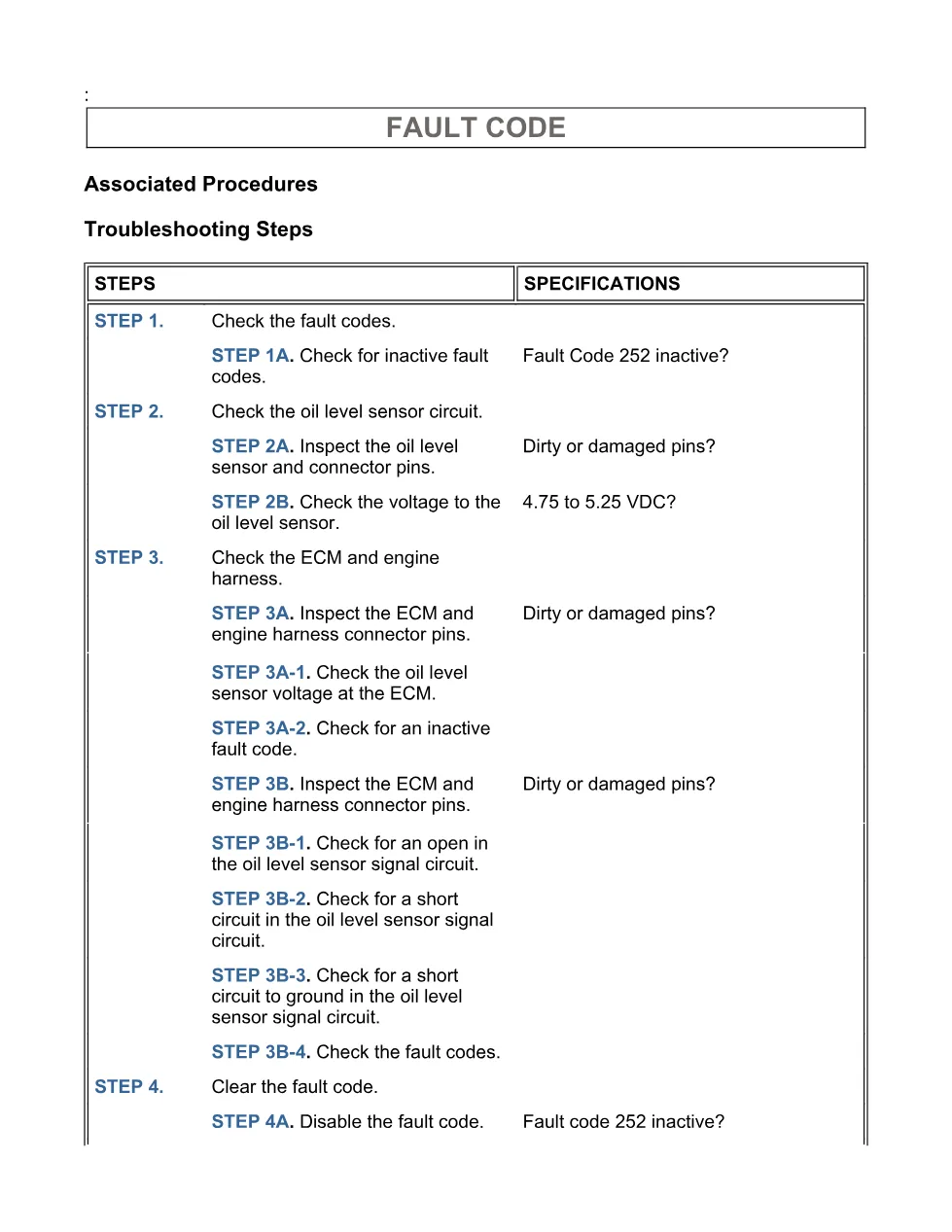
- Guided Step 1 – Check the fault codes.
- Guided Step 2 – Check the oil level sensor and circuit.
- Guided Step 3 – Check the ECM and engine harness.
- Guided Step 4B – Clear the inactive fault codes.
Applicable truck models
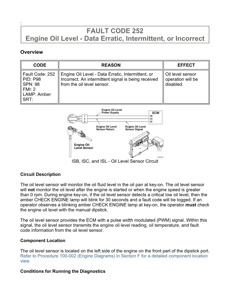
This file applies to Cummins ISB6.7 CM2150 engines from the 2007-09 group and the Fault Code 252 diagnostic procedure. The extract identifies the sensor as located on the left side of the engine at the front part of the dipstick port, and it also names ISB, ISC, and ISL oil level sensor circuit coverage. For manufacturer information, visit Cummins official website.
Who needs this Cummins oil level sensor manual
Workshop owners, diesel mechanics, and fleet technicians need this Cummins oil level sensor manual when Fault Code 252 is active or inactive and the oil level sensor operation is disabled. It supports checks for sensor power, return, signal wiring, ECM connector pins, engine harness faults, shorts to ground, and inactive fault code clearing.
The diagnostic flow starts with INSITE™ electronic service tool fault-code checks, then moves through connector inspection, 4.75 to 5.25 VDC supply testing, ECM connector voltage checks, signal circuit resistance checks, and final clearing of inactive codes. Possible causes listed in the file include missing ECM power to the sensor, open return circuit, open or shorted signal circuit, low voltage from the primary engine ECM, and a damaged oil level sensor. Full PDF available in the DiagTechPro manuals library, free account required to download.
Related manuals library

Sản phẩm liên quan cho hãng này
Cùng brand theo taxonomy hiện có trong catalog WooCommerce.

Cummins Calterm Version 5.16 – Advanced ECM Control and Precision Tuning for Cummins Engines

Cummins INSITE 9.3 – The Essential Diagnostic Tool for Cummins Engines

Cummins InCal CE – The Calibration and Configuration Tool for Cummins Engines


