
This Cummins exhaust pressure fault document is a diagnostic troubleshooting manual for Fault Code 2374 on the exhaust gas pressure sensor circuit. It explains the voltage-below-normal condition, sensor circuit checks, ECM and harness inspections, and final fault-code clearing steps for the listed Cummins engine coverage.
Official Cummins exhaust pressure fault document details
| Brand | Cummins |
|---|---|
| Model coverage | ISB6.7 CM2150 (2007-09) |
| System/Group | DTCs; ISB, ISC, and ISL – Exhaust Gas Pressure Circuit |
| Year/Revision | Last Modified: 20-Jul-2010 |
| Pages | 15 |
| File size | 0.3 MB |
| Format | |
| Language | English |
Document table of contents
- Overview
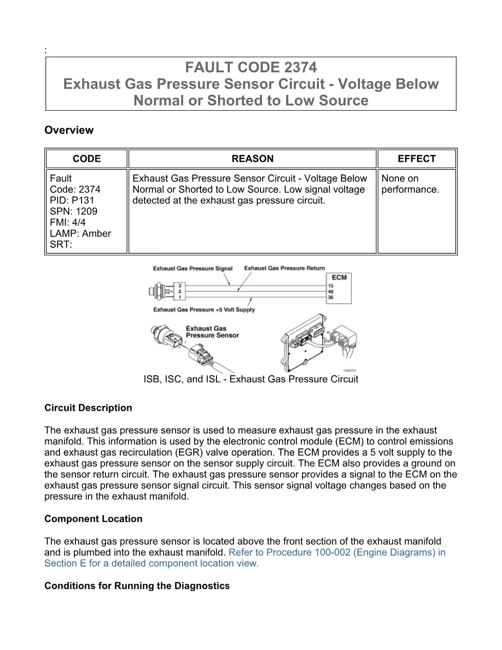
- Circuit Description
- Component Location
- Conditions for Running the Diagnostics
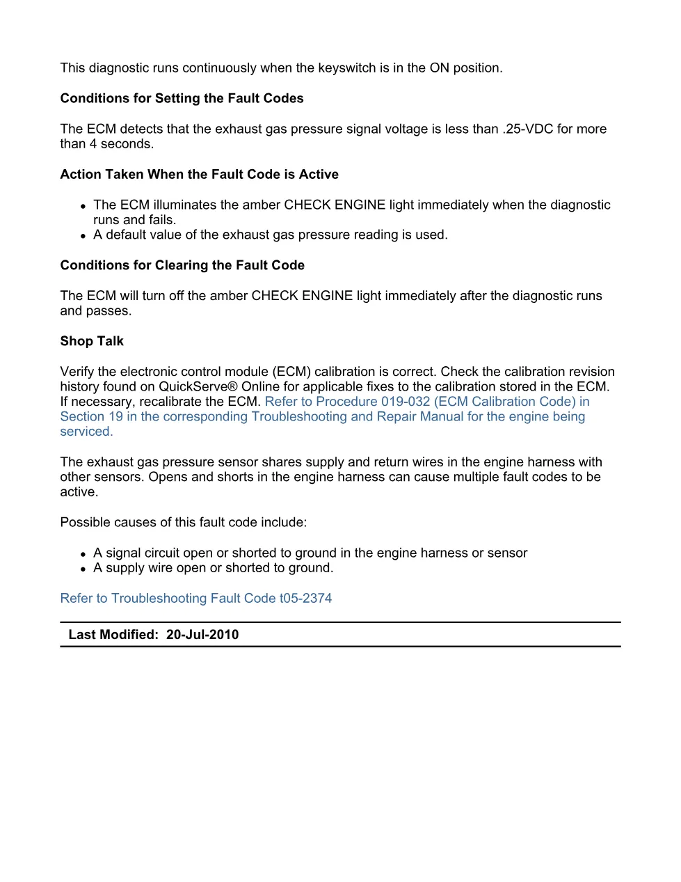
- Conditions for Setting the Fault Codes
- Action Taken When the Fault Code is Active
- Conditions for Clearing the Fault Code
- Shop Talk
- Associated Procedures
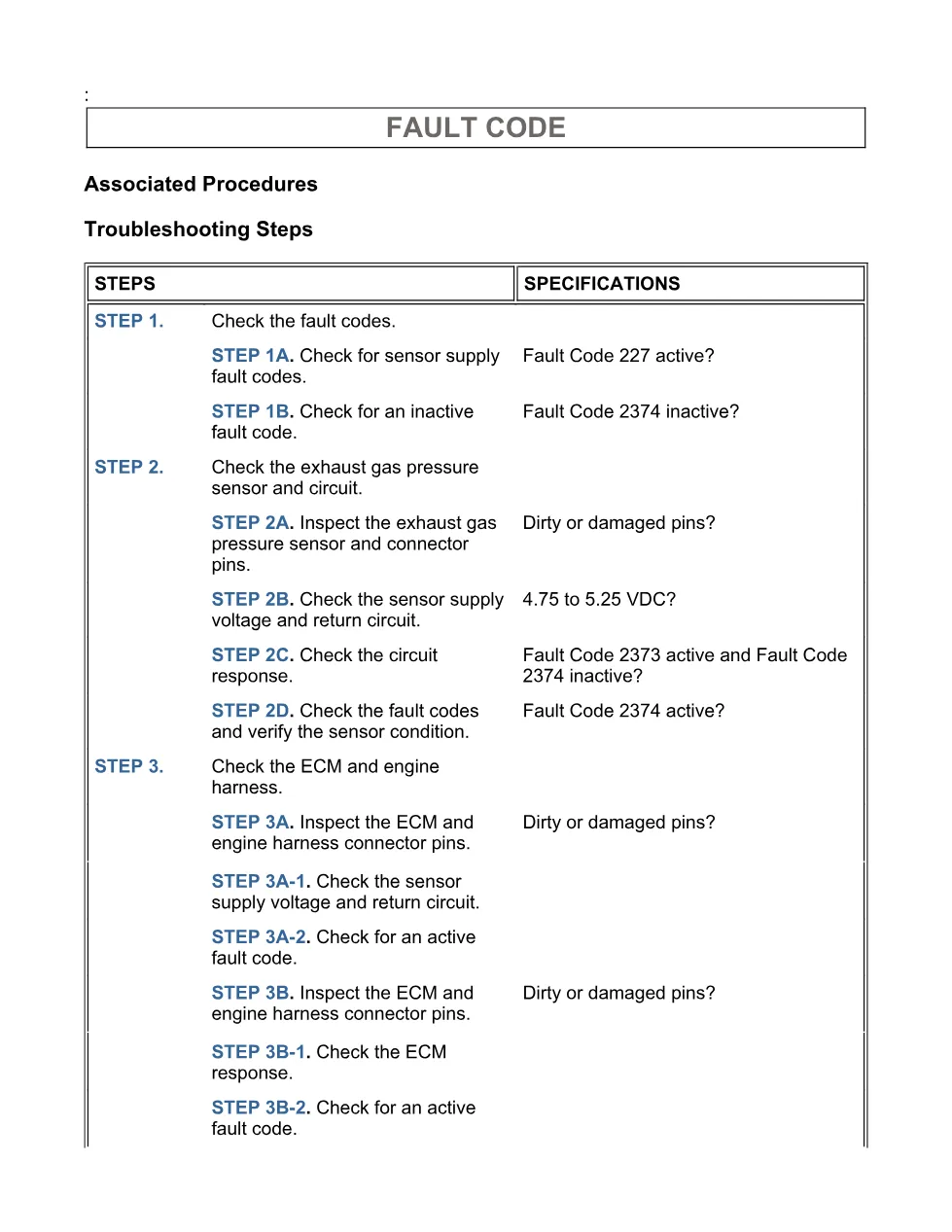
- Troubleshooting Steps
- Guided Step 1 – Check the fault codes.
- Guided Step 2 – Check the exhaust gas pressure sensor and circuit.
- Guided Step 3 – Check the ECM and engine harness.
- Guided Step 4 – Clear the fault code.
Applicable truck models
This file applies to Cummins ISB6.7 CM2150 (2007-09) diagnostic coverage and references the ISB, ISC, and ISL exhaust gas pressure circuit. The document identifies the exhaust gas pressure sensor above the front section of the exhaust manifold, plumbed into the exhaust manifold, and directs users to Procedure 100-002 for engine diagram location views. For official manufacturer information, visit Cummins official website.
Who needs this Cummins exhaust pressure fault manual
Workshop technicians, diesel mechanics, and fleet service managers use this Cummins exhaust pressure fault manual when an amber CHECK ENGINE light is linked to Fault Code 2374, PID P131, SPN 1209, FMI 4/4. It is most useful when diagnosing a low signal voltage condition below .25-VDC for more than 4 seconds on the exhaust gas pressure sensor signal circuit.
The troubleshooting flow starts by reading fault codes with INSITE™ electronic service tool and checking whether Fault Code 227 is active or Fault Code 2374 is inactive. It then moves through exhaust gas pressure sensor connector inspection, sensor supply voltage and return circuit checks, and circuit response tests using jumper wires between SUPPLY and SIGNAL pins. The manual gives the expected 4.75 to 5.25 VDC specification and uses Fault Code 2373 activity as part of the circuit response decision path.
Later procedures cover ECM connector and engine harness connector pin inspection, including loose connectors, corrosion, bent or broken pins, pushed-back pins, moisture, damaged seals, wire insulation damage, broken connector shells, and damaged locking tabs. Repair paths reference Procedure 019-361 for component connector and pin inspection, Procedure 019-043 for engine wiring harness repair, Procedure 019-031 for Electronic Control Module replacement after authorization, and Procedure 019-362 for inactive or intermittent fault codes.
Full PDF available in the DiagTechPro manuals library, free account required to download.
Related manuals library
Sản phẩm liên quan cho hãng này
Cùng brand theo taxonomy hiện có trong catalog WooCommerce.

Cummins Calterm Version 5.16 – Advanced ECM Control and Precision Tuning for Cummins Engines

Cummins INSITE 9.3 – The Essential Diagnostic Tool for Cummins Engines

Cummins InCal CE – The Calibration and Configuration Tool for Cummins Engines


