
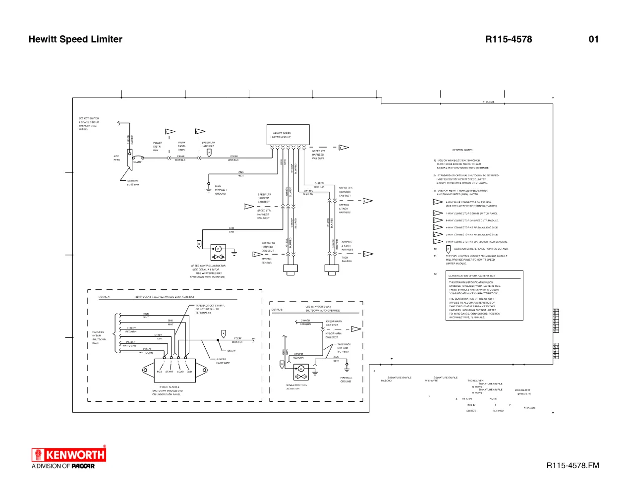
This Hewitt Speed Limiter wiring diagram, publication R115-4578, documents how the Hewitt vehicle and engine speed limiter is connected on Kenworth trucks fitted with the Caterpillar 3406B engine. The single-sheet schematic traces every circuit between the limiter module, the power distribution box and the sensors that report road speed and engine rpm, giving a technician a complete map of the system before any probe is placed.
What the wiring diagram covers — Hewitt Speed Limiter
The drawing maps the Hewitt Speed Limiter module, the speed control actuator, the speedometer and tachometer sensors, and the 10 AMP accessory feed taken from the ignition buss bar through the power distribution box. Circuit designations such as G150SU (BLU/RED), P52AF (WHT/BLK), C118SD (RED/GRN) and P144AF (WHT/LT GRN) are called out at each connector, so a technician can follow a fault from the cab section into the engine section of the harness without guessing wire colours or terminal numbers.
Kysor shutdown override details — Hewitt Speed Limiter
Detail A and Detail B on the sheet cover installations that use the Kysor 2-way shutdown auto override, showing the splice, jumper and hand-wired harness changes required, including which circuits to tape back and which terminals to leave unwired. General notes on the print state the drawing applies to W900B/L/S, T600, T800 and C500B chassis with the CAT 3406B engine, with or without the Kysor shutdown, and that standard or optional shutdown is to be wired independently of the limiter except where the drawing shows otherwise.
Connector reference for the speed limiter
The general notes on this Hewitt Speed Limiter wiring print also identify each connector by location, which speeds up back-probing in the field:
- 8-way blue connector on the PD box
- 1-way connector behind the switch panel
- 8-way connector on the speed limiter module
- 4-way connector at the firewall, engine side
- 2-way connectors at the speedometer and tachometer sensors
Using the diagram in the shop
Because the sheet doubles as both a vehicle speed and an engine rpm limiter reference, the Hewitt Speed Limiter wiring drawing is the correct starting point before testing any circuit. Confirm the accessory feed at the PD box, then work outward to the actuator and sensors, checking each connector against the print. Kenworth publishes these electrical drawings through its dealer network; corporate and build data are available from the Kenworth truck brand site. For related electrical prints, browse the DiagTechPro manuals library.
Applies to these truck models
This is the manufacturer document shared across 4 model families. It applies to:
- Kenworth C5
- Kenworth T6
- Kenworth T8
- Kenworth W9
Related manuals library
Sản phẩm phổ biến từ DiagTechPro
Gợi ý chung: các sản phẩm phổ biến của shop, không phải sản phẩm được gán cho hãng của tài liệu này.

Full Diesel Laptop Pack – All-in-One Diagnostic Solution for Diesel Technicians

ALLISON TCM REFLASH

ALLISON DOC


