

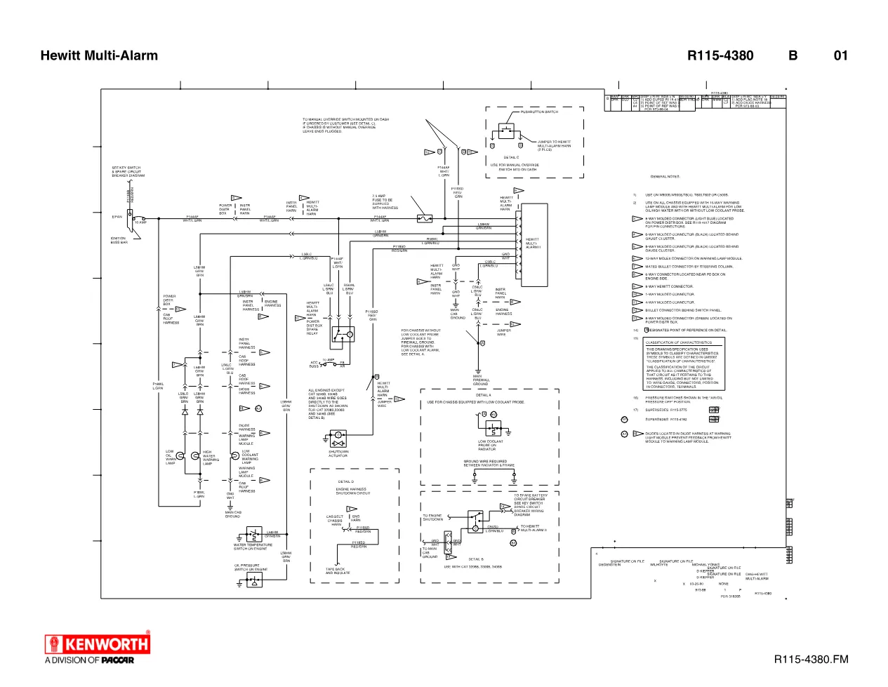
The Kenworth Hewitt Multi-Alarm wiring diagram, publication R115-4380, shows the engine-protection alarm and shutdown circuits that monitor coolant temperature, oil pressure and coolant level and can shut the engine down when a limit is exceeded. It is a single-sheet electrical print aimed at technicians who need to trace a fault in the warning and shutdown system rather than replace parts on guesswork.
Sensors and warning devices — Kenworth Hewitt
The schematic wires the water temperature switch and the oil pressure switch on the engine, plus the low coolant probe on the radiator, into the warning lamp module. From there, circuit L58HW (GRN/BRN) drives the shutdown actuator, while the low-coolant and high-water warning lamps are fed through the instrument panel and cab roof harnesses. The drawing also notes that a ground wire is required between the radiator and the frame for the coolant probe to read correctly, a detail that is easy to miss during a repair.
Power feed and override — Kenworth Hewitt
Power for the Kenworth Hewitt Multi-Alarm harness is taken through a 10 AMP feed from the power distribution box spare relay and the ignition buss bar. Detail B on the print covers installations that use the CAT 3208B, 3306B or 3406B engines and calls for a 7.5 AMP fuse supplied with the harness. Detail C documents the optional manual override pushbutton switch mounted on the dash, with jumper wires run to the Multi-Alarm harness in two places so the operator can override the shutdown when needed.
Using the Multi-Alarm diagram
Because every protection input is shown as a discrete circuit, this Kenworth Hewitt Multi-Alarm reference lets a workshop confirm each sensor before condemning the warning lamp module. A logical test sequence is:
- Verify the ground wire between radiator and frame is present
- Confirm P144AF (WHT/LT GRN) and L56LC (LT GRN/BLU) routing to the module
- Check P118SD (RED/GRN) into the engine shutdown circuit
- Confirm the warning lamps respond before the actuator fires
Working through the inputs in that order isolates whether a false shutdown comes from a sensor, the wiring, or the module itself. Kenworth distributes these electrical drawings through authorized dealers; general product information is published on the official Kenworth website. Find companion prints in the DiagTechPro manuals library.
Applies to these truck models
This is the manufacturer document shared across 4 model families. It applies to:
- Kenworth C5
- Kenworth T6
- Kenworth T8
- Kenworth W9
Related manuals library
Sản phẩm phổ biến từ DiagTechPro
Gợi ý chung: các sản phẩm phổ biến của shop, không phải sản phẩm được gán cho hãng của tài liệu này.

Full Diesel Laptop Pack – All-in-One Diagnostic Solution for Diesel Technicians
ALLISON TCM REFLASH

ALLISON DOC