
This document is a Cummins fault code 294 troubleshooting file for the OEM auxiliary temperature sensor input circuit. It explains the circuit description, possible causes, guided diagnostic checks, connector inspection, harness resistance tests, and final fault clearing steps using INSITE™ electronic service tool.
Official Cummins fault code 294 document details
| Brand | Cummins |
|---|---|
| Model coverage | ISB6.7 CM2150 (2007-09); extract also labels FAULT CODE 294 (QSB3.3) |
| System/Group | DTCs; Auxiliary Temperature Sensor Input 1 Circuit |
| Publication no. | Not shown |
| Year/Revision | Last Modified: 20-Jul-2010 |
| Pages | 12 |
| File size | 0.3 MB |
| Format | |
| Language | English |
Document table of contents
- Overview
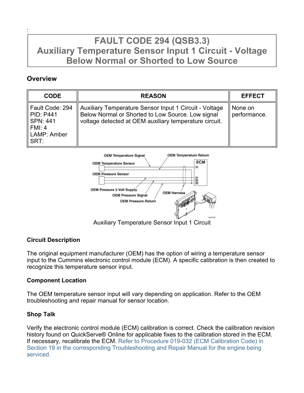
- Circuit Description
- Component Location
- Shop Talk
- FAULT CODE 294 (QSB3.3)
- Auxiliary Temperature Sensor Input 1 Circuit – Voltage Below Normal or Shorted to Low Source
- Possible causes of this fault code
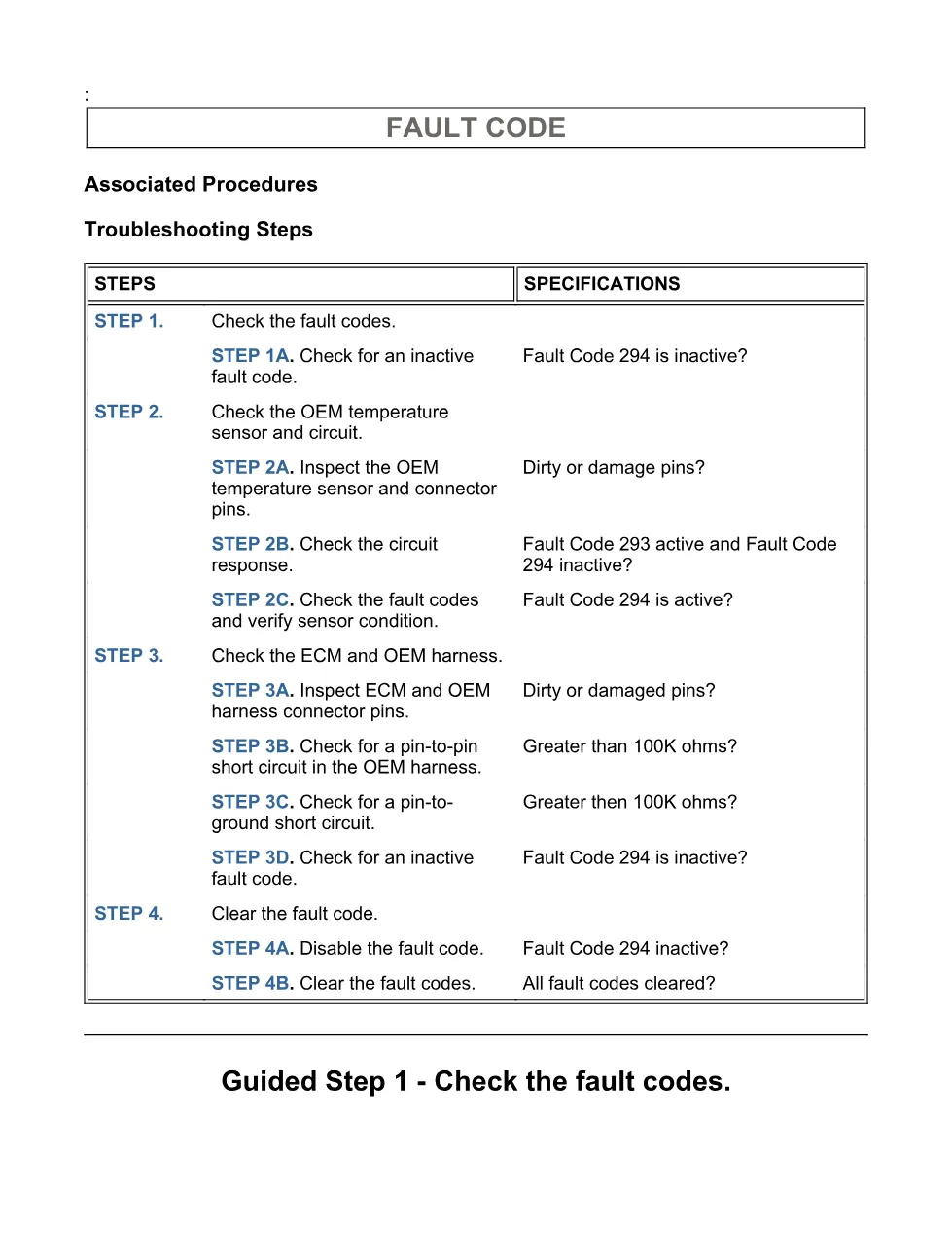
- Associated Procedures
- Troubleshooting Steps
- Guided Step 1 – Check the fault codes.
- Guided Step 2 – Check the OEM temperature sensor and circuit.
- Guided Step 3 – Check the ECM and OEM harness.
- Guided Step 4 – Clear the fault code.
Applicable truck models
This file applies to Cummins engines and OEM installations covered by the listed group: ISB6.7 CM2150 (2007-09), with the extract also identifying FAULT CODE 294 (QSB3.3). The OEM temperature sensor input location varies by application, so the document directs technicians to the OEM troubleshooting and repair manual for the sensor location and to QuickServe® Online for ECM calibration revision history. Manufacturer information is available from Cummins official website.
Who needs this Cummins fault code 294 manual
Workshop owners, diesel mechanics, and fleet technicians need this Cummins fault code 294 manual when an amber lamp fault reports PID P441, SPN 441, FMI 4, with low signal voltage detected at the OEM auxiliary temperature circuit. The procedure is aimed at confirming whether the fault is caused by the sensor, connector condition, OEM harness, signal short to return or ground, or ECM-related checks.
The diagnostic flow starts with reading active or inactive fault codes through INSITE™ electronic service tool. It then checks the OEM temperature sensor connector for loose connectors, corroded pins, bent or broken pins, moisture, missing seals, dirt, wire insulation damage, shell damage, and locking tab damage. If connector removal changes the circuit response, the procedure notes that the connection may have corrected the problem.
For harness diagnosis, the file gives pin-to-pin and pin-to-ground short circuit checks. The technician disconnects the OEM harness from the ECM connector and disconnects the OEM temperature sensor, then measures resistance from the OEM temperature SIGNAL pin to other pins or to ground. The expected specification shown is greater than 100K ohms. Failed checks direct repair or replacement of the OEM harness under Procedure 019-071, while repeated unresolved checks can lead to authorization steps for ECM replacement.
Full PDF available in the DiagTechPro manuals library, free account required to download.
Related manuals library

Sản phẩm liên quan cho hãng này
Cùng brand theo taxonomy hiện có trong catalog WooCommerce.

Cummins Calterm Version 5.16 – Advanced ECM Control and Precision Tuning for Cummins Engines

Cummins INSITE 9.3 – The Essential Diagnostic Tool for Cummins Engines

Cummins InCal CE – The Calibration and Configuration Tool for Cummins Engines


