
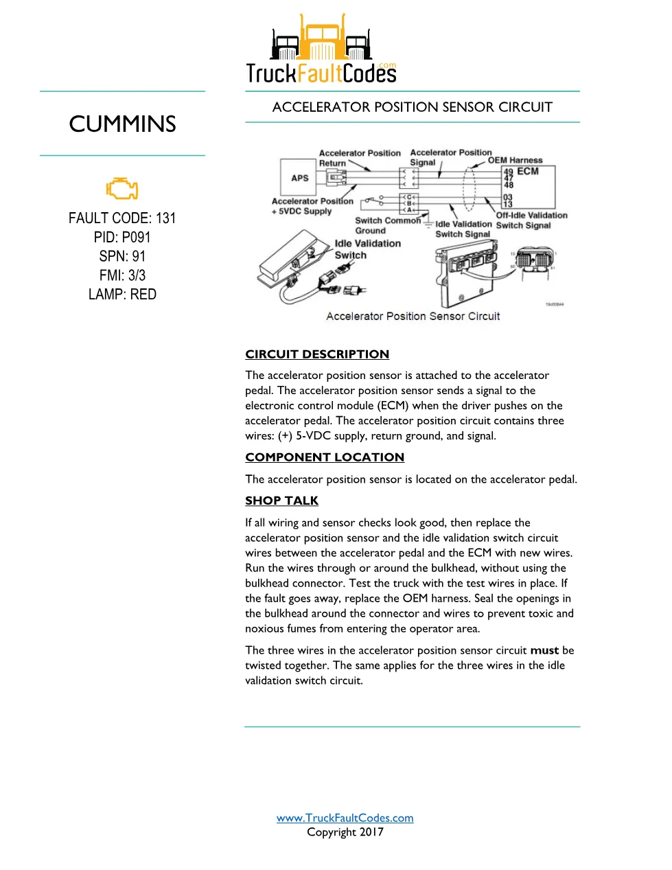
Cummins ISM code 131 is the DiagTechPro reference page for this Cummins diagnostic fault code 131 document, a 8-page PDF sourced from TruckFaultCodes.com (Copyright 2017) that covers the accelerator position sensor circuit. The accelerator position sensor is attached to the accelerator pedal. The accelerator position sensor sends a signal to the electronic control module (ECM) when the driver pushes on the accelerator pedal. The accelerator position circuit contains three wires: (+) 5-VDC supply, return ground, and signal. When the condition is detected the ECM logs the fault and turns on the red warning lamp to alert the driver and technician.
Cummins ISM code 131 document details
| Brand | Cummins |
|---|---|
| Model coverage | ISM CM570 (1999-02) / DTCs; ISX CM570 (1999-02) / DTCs; Signature CM570 (1999-02) / DTCs |
| System / Group | ISM CM570 (1999-02) / DTCs |
| Fault identifier | Code 131 (PID P091, SPN 91, FMI 3) |
| Warning lamp | Red |
| Source | TruckFaultCodes.com |
| Year / Revision | Copyright 2017 |
| Pages | 8 |
| File size | 0.4 MB |
| Format | |
| Language | English |
Document table of contents
- Circuit Description
- Component Location
- Shop Talk
- Troubleshooting Steps
- Repair verification and clearing fault codes
Applicable truck models
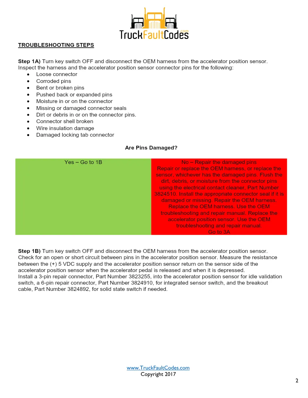
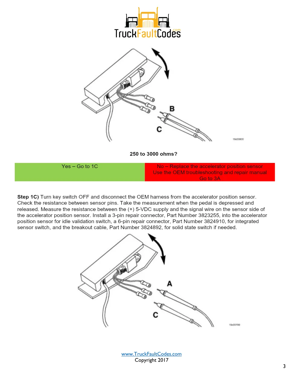
This document applies to Cummins ISM CM570 (1999-02) / DTCs; ISX CM570 (1999-02) / DTCs; Signature CM570 (1999-02) / DTCs electronic engines used in on-highway and vocational trucks. The accelerator position sensor is located on the accelerator pedal. The troubleshooting section walks through connector and pin inspection, engine-harness resistance measurements and pin-to-pin continuity checks, and ends with a road test that confirms the code is inactive and all fault codes are cleared. Because the same procedure isolates the sensor, the harness and the ECM in turn, it prevents replacing parts that are still good. Verify engine calibration and coverage against the official Cummins engine support site before ordering parts.
Who needs this Cummins ISM code 131 manual
Any mechanic or workshop owner diagnosing ISM code 131 needs this PDF to follow the factory circuit and resistance checks in the correct order. If all wiring and sensor checks look good, then replace the accelerator position sensor and the idle validation switch circuit wires between the accelerator pedal and the ECM with new wires. Run the wires through or around the bulkhead, without using the bulkhead connector.
Related manuals library
The full PDF is available in the DiagTechPro manuals library; a free account is required to download.
Sản phẩm liên quan cho hãng này
Cùng brand theo taxonomy hiện có trong catalog WooCommerce.

Cummins INSITE 9.3 – The Essential Diagnostic Tool for Cummins Engines

Cummins Calterm Version 5.16 – Advanced ECM Control and Precision Tuning for Cummins Engines

Cummins InCal CE – The Calibration and Configuration Tool for Cummins Engines


