
This document is a Cummins CM2250 wiring reference for ISB6.7 engine performance circuits. It contains eight wiring diagram sheets showing ECM connectors, sensor circuits, aftertreatment components, switches, lamps, relays, grounds, and data link connections. The file is supplied as an English PDF for workshop electrical diagnosis.
Official Cummins CM2250 wiring document details
| Brand | Cummins |
|---|---|
| Model coverage | ISB6.7 – CM 2250 |
| System/Group | ISB6.7 CM2250 (2010-12) / Wiring Diagrams |
| Year/Revision | Unknown |
| Pages | 8 |
| File size | 0.8 MB |
| Format | |
| Language | English |
Document table of contents
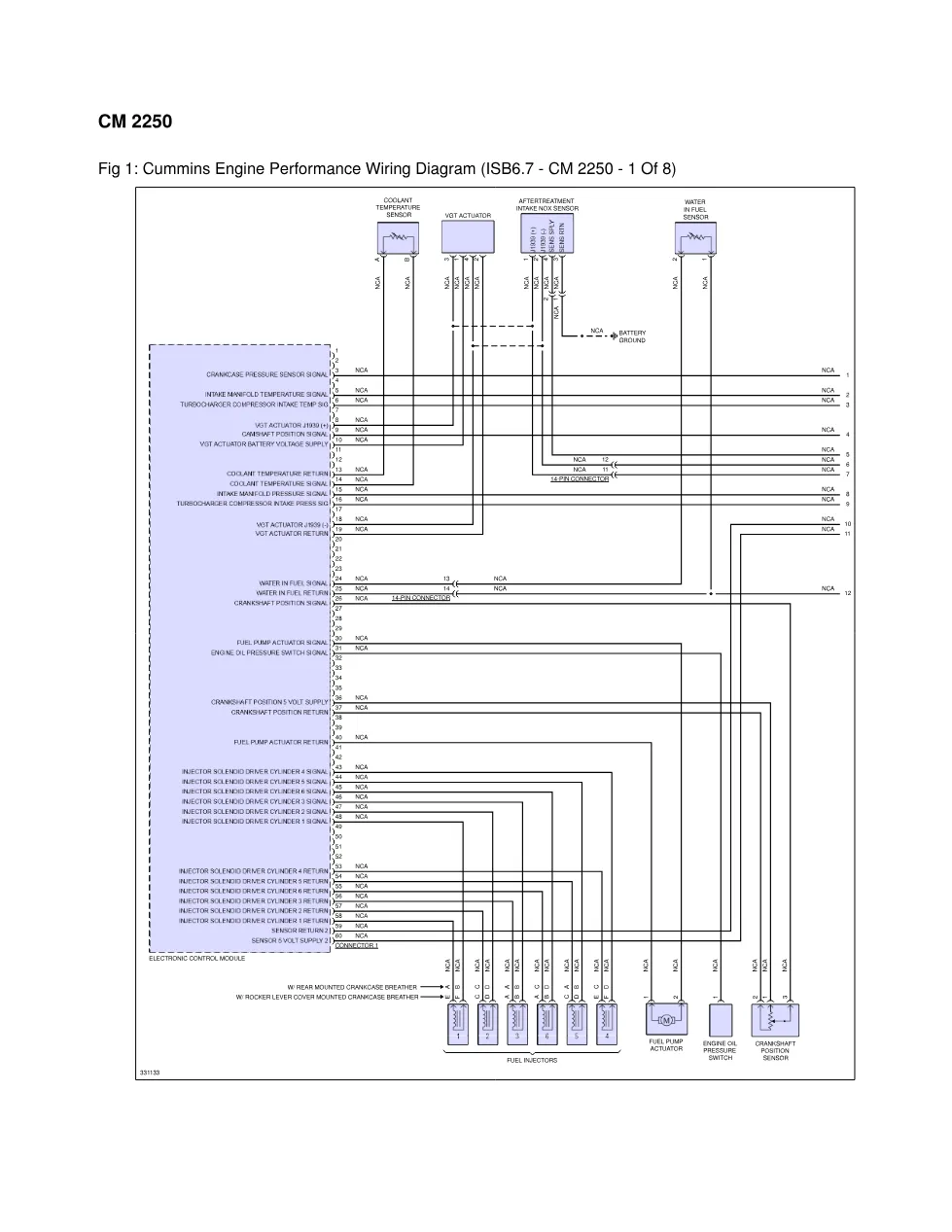
- Fig 1: Cummins Engine Performance Wiring Diagram (ISB6.7 – CM 2250 – 1 Of 8)
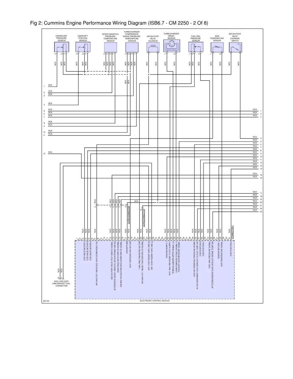
- Fig 2: Cummins Engine Performance Wiring Diagram (ISB6.7 – CM 2250 – 2 Of 8)
- Fig 3: Cummins Engine Performance Wiring Diagram (ISB6.7 – CM 2250 – 3 Of 8)
- Fig 4: Cummins Engine Performance Wiring Diagram (ISB6.7 – CM 2250 – 4 Of 8)
- Fig 5: Cummins Engine Performance Wiring Diagram (ISB6.7 – CM 2250 – 5 Of 8)
- Fig 6: Cummins Engine Performance Wiring Diagram (ISB6.7 – CM 2250 – 6 Of 8)
- Fig 7: Cummins Engine Performance Wiring Diagram (ISB6.7 – CM 2250 – 7 Of 8)
- Fig 8: Cummins Engine Performance Wiring Diagram (ISB6.7 – CM 2250 – 8 Of 8)
Applicable truck models
This PDF applies to Cummins ISB6.7 engines using the CM 2250 electronic control system, as identified by the document title and figure captions. The diagrams cover engine performance wiring around the Electronic Control Module, fuel injectors, VGT actuator, coolant temperature sensor, fuel rail pressure sensor, camshaft position sensor, crankshaft position sensor, intake manifold pressure/temperature sensor, exhaust gas pressure sensor, and EGR differential pressure sensor. Aftertreatment coverage includes the aftertreatment intake NOx sensor, aftertreatment outlet NOx sensor, diesel exhaust fluid controller, DEF tank level sensor, DEF tank temperature sensor, DEF dosing valve, DEF line heaters, diesel particulate filter regeneration switches, DPF temperature sensor interface module, and DPF differential pressure/outlet pressure sensor. Vehicle interface circuits shown include SAE J1939 data link/service tool connector, 9-pin Deutsch connector, key switch, accelerator pedal assembly, vehicle speed sensor, tachometer, fan clutch, fan speed sensor, intake air heater relay, braking lamp relay, warning lamps, stop lamp, wait to start lamp, and HEST lamp. For manufacturer information, visit Cummins official website.
Who needs this Cummins CM2250 wiring manual
Mechanics, diesel electricians, and workshop owners need this Cummins CM2250 wiring manual when tracing ISB6.7 electrical faults, checking connector pins, or diagnosing sensor, actuator, aftertreatment, J1939, lamp, switch, relay, and ground circuits. It is useful when the repair requires circuit identification rather than mechanical specifications.
The full PDF is available in the DiagTechPro manuals library, free account required to download.
Related manuals library
Sản phẩm liên quan cho hãng này
Cùng brand theo taxonomy hiện có trong catalog WooCommerce.

Cummins INSITE 9.3 – The Essential Diagnostic Tool for Cummins Engines

Cummins Calterm Version 5.16 – Advanced ECM Control and Precision Tuning for Cummins Engines

Cummins InCal CE – The Calibration and Configuration Tool for Cummins Engines


