SPN 3242 FMI 8 is the Detroit DD Series fault-code procedure for a diesel oxidation catalyst inlet temperature signal spike. This 2-page diagnostic PDF documents the fault, its monitored circuit on the diesel oxidation catalyst (DOC) inlet temperature sensor, and the exact troubleshooting steps a technician follows to confirm and repair the failure.
Official document details
| Brand | Detroit |
| Model coverage | DD Series (EPA 2007-Current); Series 60 DDEC VI |
| System / Group | DD Series / DTCs |
| SPN (fault code) | 3242 |
| FMI (failure mode) | 8 |
| Emission family | EPA10 / GHG14 calibration |
| Source | Detroit Power Service Literature (Copyright © 2017) |
| Pages | 2 |
| File size | 0.28 MB |
| Format | |
| Language | English |
Document table of contents
- Fault code identification (SPN 3242, failure mode 8)
- Fault note on intermittent wiring
- Troubleshooting steps
- Harness wiggle test and drag test
Applicable truck models
This procedure applies to Detroit DD13, DD15 and DD16 engines in the DD Series (EPA 2007-Current) range and the equivalent Series 60 (DDEC VI) platform, as fitted to Freightliner and Western Star trucks. Confirm the EPA10 / GHG14 emission family matches the truck before following the steps; full model and coverage data is published on the Detroit official website.
Who needs this SPN 3242 FMI 8 manual
Diesel technicians, fleet workshops and mobile mechanics diagnosing an intermittent DOC inlet temperature signal spike on EPA10 or GHG14 Detroit engines need this reference to test the circuit correctly with a diesel diagnostic tool instead of replacing parts by guesswork.
SPN 3242 FMI 8 repair steps explained
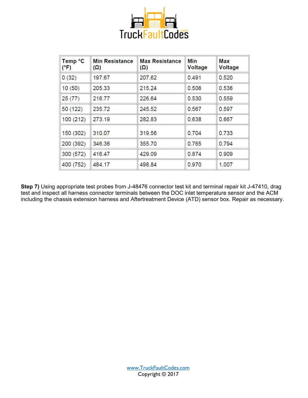
This fault indicates the Aftertreatment Control Module (ACM) detected a sudden temperature shift on the DOC inlet temperature sensor, most often from an intermittent wiring concern such as poor terminal fit, corrosion or chafing. The technician confirms no active FMI 3 or FMI 4 fault, then monitors the DOC inlet temperature parameter at pin 107 while wiggle-testing the harness to catch voltage spikes. Sensor resistance is checked between pins 1 and 2, and every connector terminal from the sensor to the ACM is drag-tested with the J-48476 connector test kit and J-47410 terminal repair kit per Detroit Power Service Literature.
The full PDF is available in the DiagTechPro manuals library; a free account is required to download it.
Related manuals library