

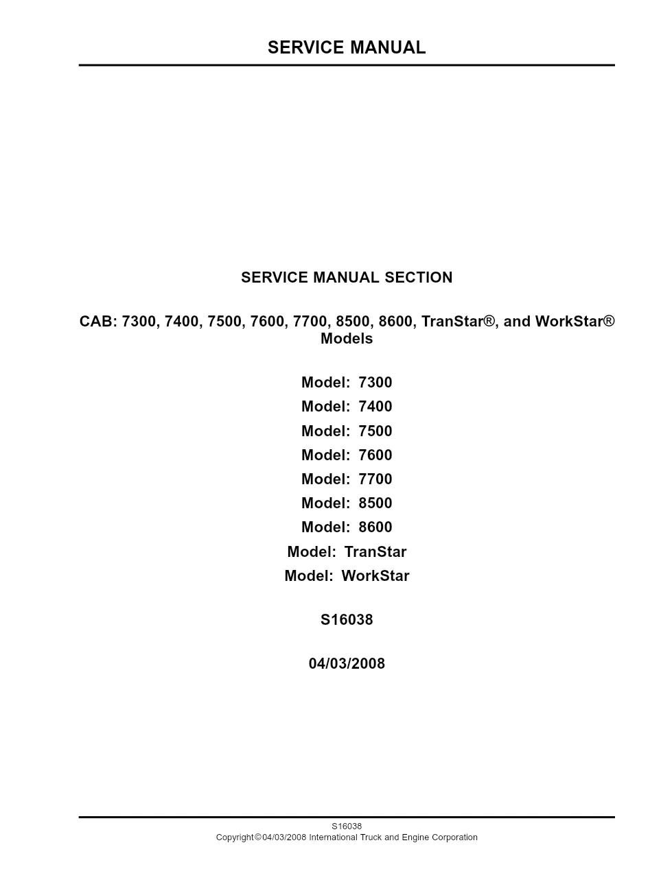
This International TranStar cab manual is the 2008 cab service section, publication S16038, covering removal and installation of cab body components on International medium and heavy trucks. It documents windshield, glass, door, headliner and cab air suspension procedures, each with the specified fasteners and torque values.
Official document details
| Brand | International Trucks |
|---|---|
| Model coverage | 7300, 7400, 7500, 7600, 7700, 8500, 8600, TranStar, WorkStar |
| System / Group | Cab — removal and installation |
| Publication no. | S16038 |
| Year / Revision | 04/03/2008 |
| Pages | 201 |
| File size | 2.2 MB |
| Format | |
| Language | English |
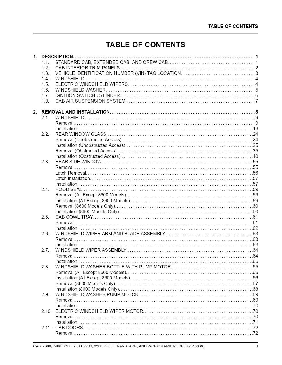
International TranStar cab manual table of contents
- Description — standard, extended and crew cab
- Windshield removal and installation
- Rear window glass (obstructed and unobstructed access)
- Rear side window, latch removal and installation
- Hood seal and cab cowl tray
- Windshield wiper arm, blade and wiper assembly
- Door trim panel and door latch
- Headliner trim panel, crew cab
- Cab air suspension and height control valve
- Torque chart
Applicable truck models covered
The procedures apply to International 7300, 7400, 7500, 7600, 7700, 8500 and 8600 models plus the TranStar and WorkStar, built with standard, extended or crew cab. Only cab body work is covered; engine, chassis and electrical repairs live in separate sections. See the manufacturer at International Trucks official website.
Who needs the International TranStar cab manual
Body shops and fleet technicians use this TranStar cab manual because it lists the correct fasteners, the ZTSE4839 interior trim tool and the torque specifications needed to remove and refit glass, doors, trim and cab air suspension parts.
Because a cracked windshield or a leaking cab seal keeps a truck off the road, the section shows each removal step with its matching figure and item callouts, so a technician can compare the illustration directly with the part in hand. It repeats the safety warnings to wear eye protection and gloves, and to keep the cutting area wet when a power knife is used so the urethane does not burn and rebond the glass. The closing torque chart lists shock absorber, air spring, lateral control rod and height control valve values for the cab air suspension, figures that are essential for a safe reassembly after any cab-off or ride-height repair.
The full PDF is available in the DiagTechPro manuals library; a free account is required to download it.
Related manuals library

Sản phẩm phổ biến từ DiagTechPro
Gợi ý chung: các sản phẩm phổ biến của shop, không phải sản phẩm được gán cho hãng của tài liệu này.

Full Diesel Laptop Pack – All-in-One Diagnostic Solution for Diesel Technicians

ALLISON TCM REFLASH

ALLISON DOC