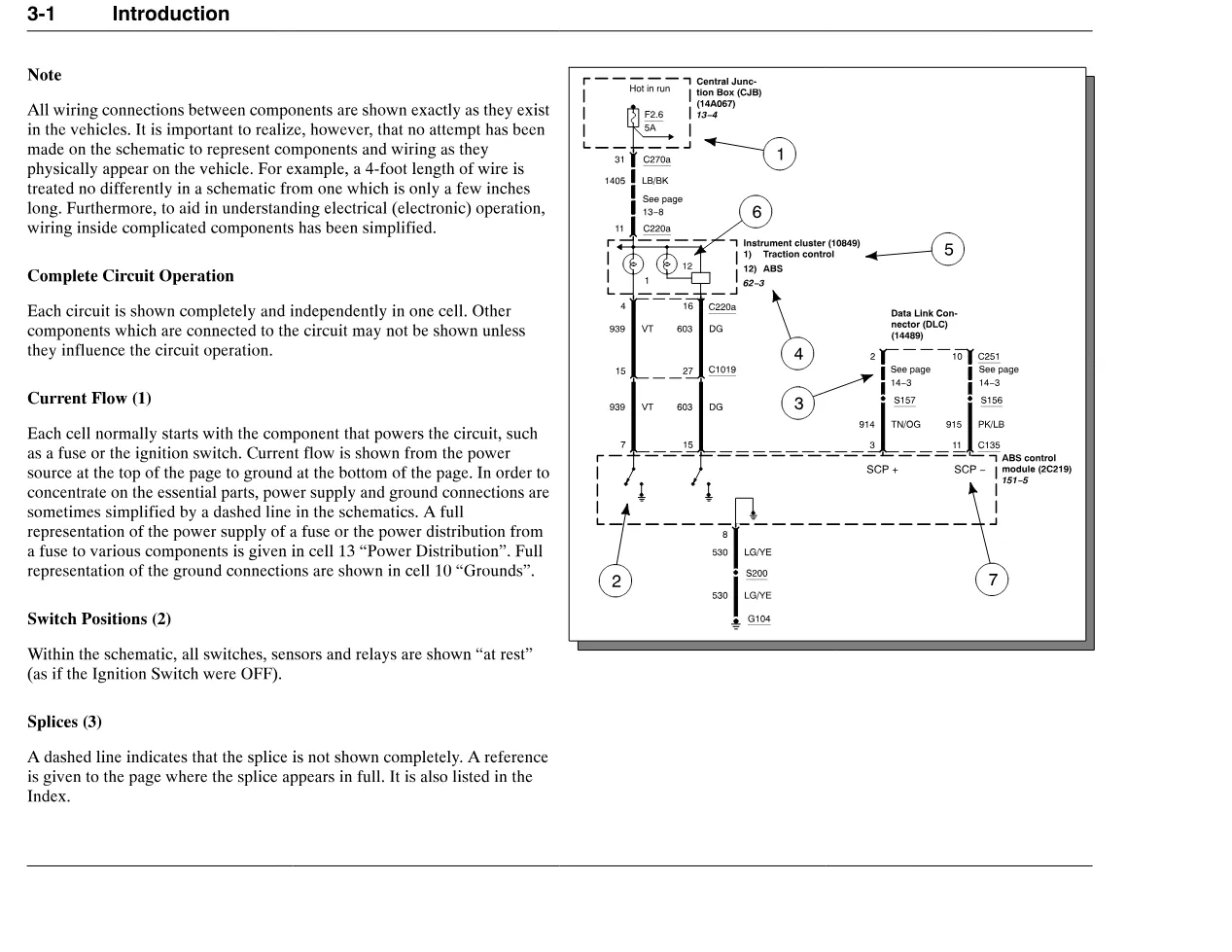
The CityStar wiring diagrams (publication S08311) are International’s complete circuit diagrams for the CF 500 and CF 600 CityStar cabover trucks. This 197-page manual shows every wiring connection exactly as it exists on the vehicle, from power distribution and grounds to the 4.5L diesel electronic engine controls. Current flow is drawn from the power source at the top of each page to ground at the bottom.
CityStar wiring diagrams document details
| Brand | International Trucks |
| Model coverage | CF 500 and CF 600 (CityStar) |
| System / Group | Wiring Diagrams / Circuit Diagrams |
| Publication no. | S08311 |
| Year / Revision | Not stated on cover |
| Pages | 197 |
| File size | 4.2 MB |
| Format | |
| Language | English |
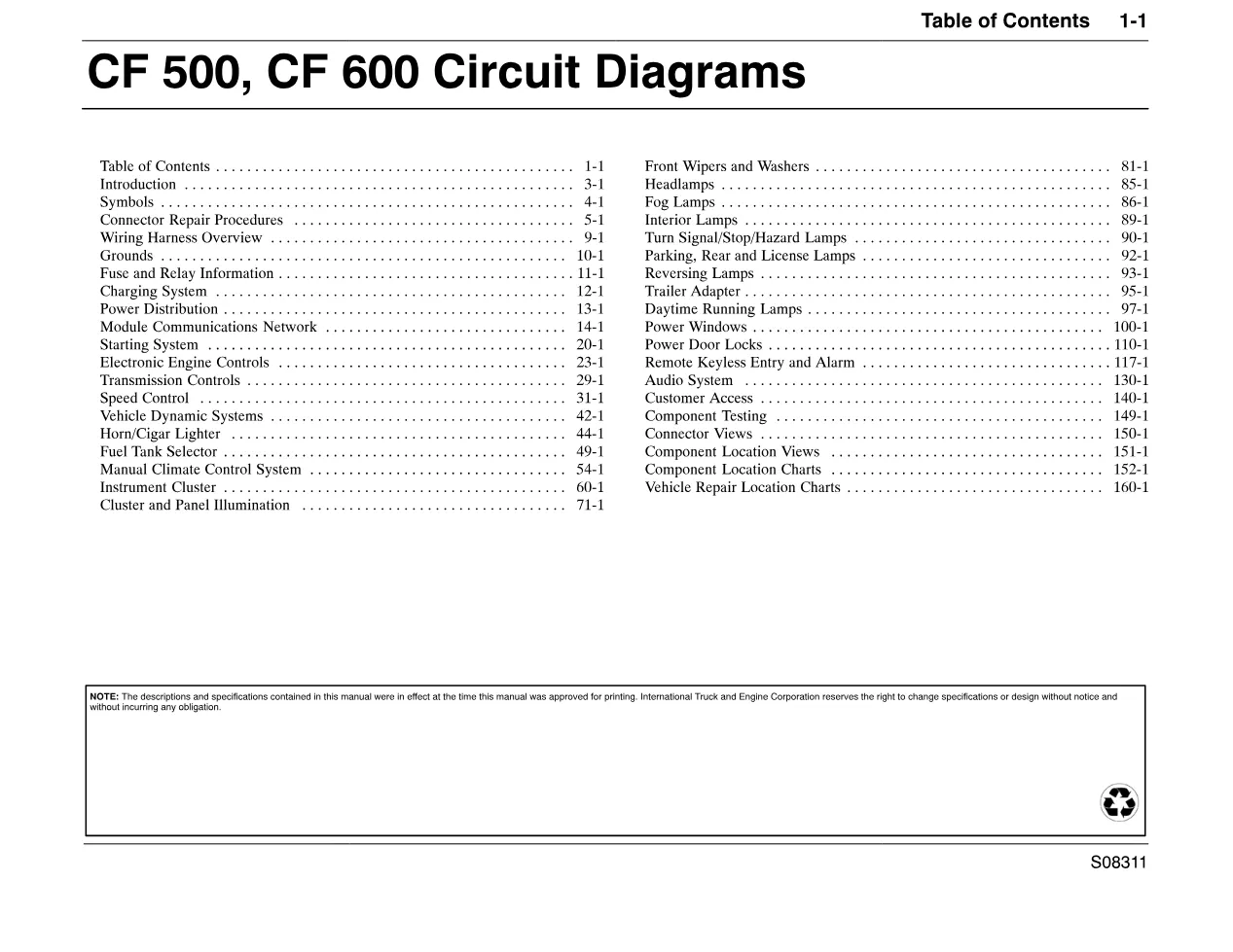
Document table of contents
- Introduction, symbols and connector repair procedures
- Wiring harness overview, grounds and fuse and relay information
- Charging system and power distribution
- Module communications network and starting system
- Electronic engine controls (4.5L diesel) and transmission controls
- Instrument cluster, headlamps, fog lamps and interior lamps
- Power windows, power door locks and remote keyless entry
- Audio system, connector views and component location charts
Applicable truck models covered
The CityStar wiring diagrams cover the CF 500 and CF 600 models fitted with the 4.5L diesel engine and its Engine Control Module (ECM). Circuits documented include the charging system, starting system, module communications network, power windows, power door locks, remote keyless entry, and the audio system with premium radio. Connector views, component location charts, and vehicle repair location codes help pinpoint the physical location of each repair on the truck. For CF-series product information, see the official International Trucks site at International Trucks.
Who needs these CityStar wiring diagrams
Auto electricians and diagnostic technicians tracing faults on CF 500 or CF 600 trucks need these diagrams to follow current flow from fuse to ground and to read connector pinouts correctly. Each circuit is shown completely and independently in one cell, and component testing and component location charts are provided for the CF 500 and CF 600.
The complete PDF is available in the DiagTechPro manuals library, free account required to download.
Related manuals library