
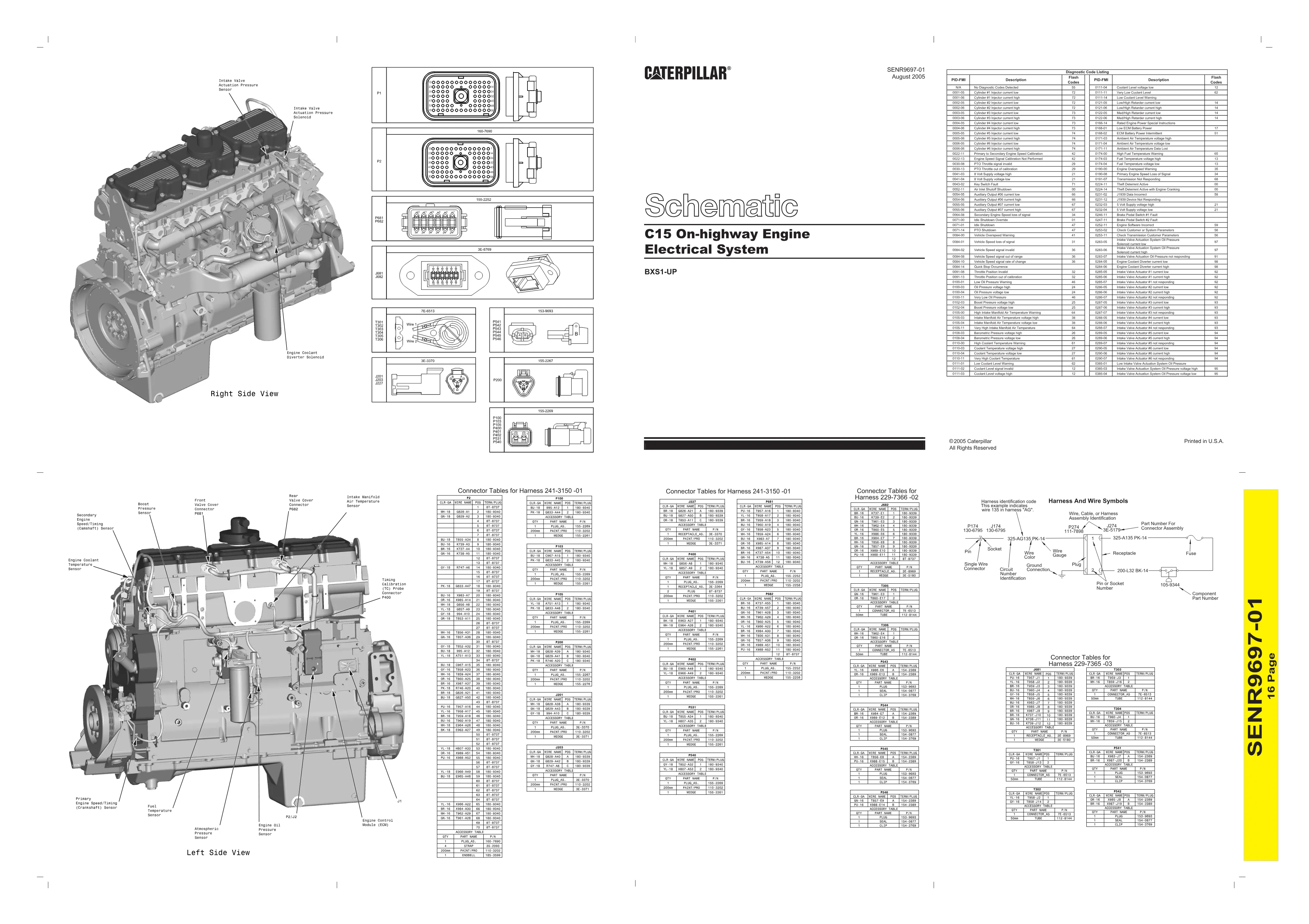
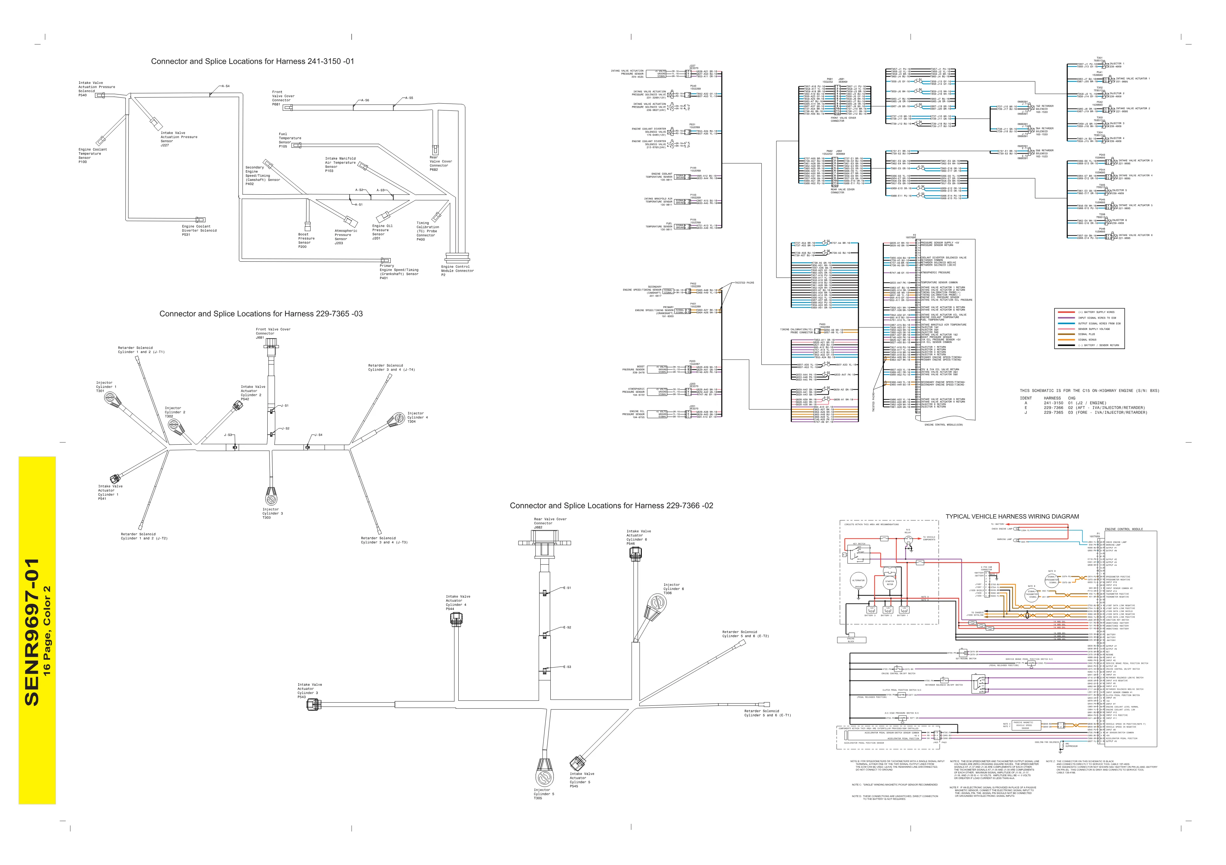
This CAT C15 wiring diagram provides the complete electrical system schematic for the Caterpillar C15 on-highway engine, serial prefix BXS1-UP. Published as SENR9697-01 in August 2005, the two-page document covers ECM connector pin-out tables, sensor and solenoid wiring, injector circuits, valve cover harness routing, and a full PID-FMI diagnostic trouble code reference list.
Official CAT C15 wiring diagram document details
| Brand | Caterpillar (CAT) |
| Model coverage | C15 On-highway Engine, BXS1-UP |
| System / Group | C11 C13 C15 Electrical System / Schematics |
| Publication no. | SENR9697-01 |
| Year / Revision | August 2005 |
| Pages | 2 |
| File size | 0.5 MB |
| Format | |
| Language | English |
Document table of contents
- Right Side View — sensor and solenoid connector locations
- Left Side View — ECM, valve cover connectors, timing calibration probe
- Engine Control Module (ECM) connector P2 pin-out table (70 pins)
- Sensor connector tables: P100 (Engine Oil Pressure), P103 (Engine Coolant Temperature), P105 (Fuel Temperature), P200 (Boost Pressure), P400 (Atmospheric Pressure), P401 (Primary Speed/Timing), P402 (Secondary Speed/Timing)
- Solenoid connector tables: P531 (Engine Coolant Diverter), P540 (Intake Valve Actuation Pressure)
- Valve cover connector tables: P681 (Front) and P682 (Rear) — 12-pin each
- Intake valve actuator connectors P541–P546 and injector connectors T301–T306
- Retarder solenoid circuits (Cylinders 1-2, 3-4, 5-6)
- Harness and wire symbol legend
- Connector and splice locations for harnesses 229-7366-02, 229-7365-03, and 241-3150-01
- PID-FMI diagnostic trouble code table with flash codes
- Vehicle interface wiring: accelerator pedal sensor, vehicle speed sensor, cruise control, service brake switch, J1939 datalink, tachometer, warning lamps
Applicable truck models
This schematic applies to Caterpillar C15 on-highway engines with serial prefix BXS1-UP. It is grouped under the C11, C13, and C15 engine family. The document references OEM-installed vehicle-side components including the accelerator pedal position sensor, passive magnetic vehicle speed sensor, clutch and brake switches, cruise control switches, retarder solenoid on/off switch, J1939 datalink connections, and warning lamps. These engines were commonly installed in Class 8 trucks from multiple OEMs. For official Caterpillar parts and service information, visit Caterpillar Support.
Who needs this CAT C15 wiring diagram manual
Diesel mechanics and workshop owners troubleshooting electrical faults, diagnostic trouble codes, injector circuits, intake valve actuator wiring, or sensor signal issues on C15 engines will find this schematic essential. The detailed connector pin-out tables with wire colors, gauge sizes, and Caterpillar part numbers enable precise harness repair and continuity testing.
The full PDF of this C15 wiring diagram is available in the DiagTechPro manuals library. A free account is required to download.
Related manuals library
Sản phẩm liên quan cho hãng này
Cùng brand theo taxonomy hiện có trong catalog WooCommerce.

CAT Perkins Pack – Premium Power & Performance by Caterpillar

CAT SIS


