
This EPA CAN troubleshooting U1122B document provides mechanics and workshop owners with a comprehensive step-by-step diagnostic procedure for isolating and resolving CAN network faults on PACCAR MX engines with EPA 2004 and EPA 2013 compliance. Published by PACCAR, this guide covers the complete methodology for diagnosing U-code (CAN-related) DTCs using DAVIE diagnostics software and standard electrical testing equipment.
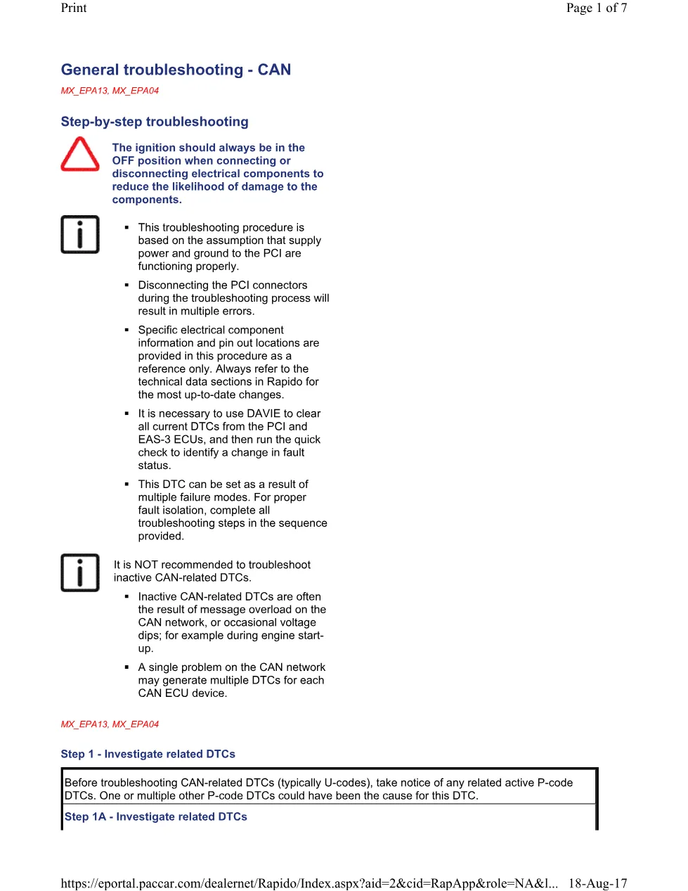
The EPA CAN troubleshooting U1122B procedure assumes supply power and ground to the PCI (Powertrain Control Interface) are functioning correctly before diagnosis begins. The document emphasizes that CAN-related DTCs can result from multiple failure modes, including aftermarket device installation, wiring faults, termination resistor failures, and voltage supply issues.
Document details and specifications — EPA CAN troubleshooting
| Brand | PACCAR |
| Model coverage | MX_EPA13, MX_EPA04 |
| System/Group | DTCs / MX Europe Engines (EPA 2004) |
| Publication number | U1122B |
| Year/Revision | 18 August 2017 |
| Pages | 7 |
| File size | 0.1 MB |
| Format | |
| Language | English |
Table of contents
- Step 1 – Investigate related DTCs (P-code investigation and aftermarket device detection)
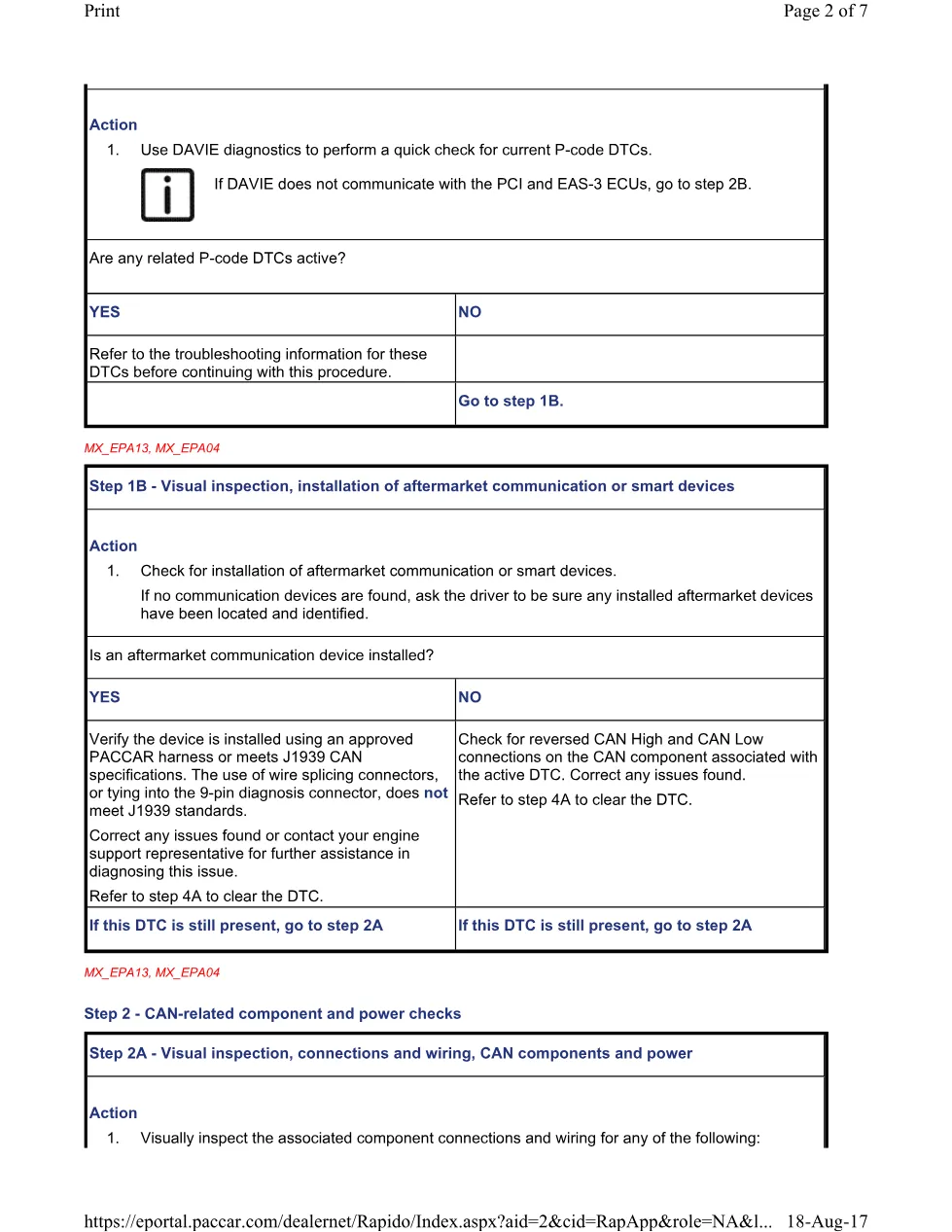
- Step 1A – Investigate related DTCs (DAVIE quick check procedure)
- Step 1B – Visual inspection, installation of aftermarket communication or smart devices
- Step 2 – CAN-related component and power checks
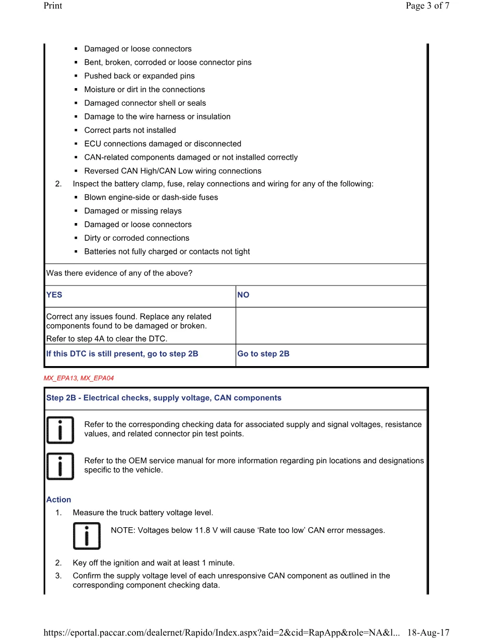
- Step 2A – Visual inspection, connections and wiring, CAN components and power
- Step 2B – Electrical checks, supply voltage, CAN components
- Step 3 – Isolate faulty CAN network or component
- Step 3A – Electrical checks, resistance, V-CAN network (60 Ω and 120 Ω termination)
- Step 3B – Electrical checks, resistance, V-CAN termination resistors
- Step 3C – Electrical checks, resistance, E-CAN termination resistors
- Step 3D – Electrical checks, resistance, A-CAN termination resistors
- Step 4 – Clear CAN-related DTCs
- Step 4A – Clear DTCs (DAVIE verification and completion)
Diagnostic procedure overview
The EPA CAN troubleshooting U1122B methodology follows a structured four-step diagnostic approach. Step 1 requires investigation of related P-code DTCs and detection of any aftermarket communication devices that may cause CAN network interference. Step 2 focuses on visual inspection of connectors, wiring, battery connections, and supply voltage verification. Step 3 isolates the fault to a specific CAN network (V-CAN, E-CAN, or A-CAN) through resistance measurements at termination points. Step 4 uses DAVIE diagnostics to verify that all DTCs have been cleared or changed to inactive status.
Critical electrical parameters in EPA CAN troubleshooting U1122B include battery voltage (minimum 11.8 V to prevent ‘Rate too low’ errors), V-CAN termination resistance of 60 Ω at the 9-pin diagnosis connector, and 120 Ω termination resistors in the PCI ECU (D420), CECU, EAS-3 ECU (D374), and VTG turbo charger actuator (L037). The guide warns that disconnecting PCI connectors during diagnosis will result in multiple false errors and recommends using approved PACCAR harnesses that meet J1939 CAN specifications rather than wire splicing connectors.
Applies to these models
This EPA CAN troubleshooting U1122B guide applies to PACCAR MX engines with EPA 2013 and EPA 2004 emissions compliance. It covers diagnostic procedures for the PCI (Powertrain Control Interface), EAS-3 (Electronic Air Suspension) ECU, CECU (Cooling Control Unit), and associated CAN network components including humidity sensors, NOx sensors, and VTG turbo charger actuators. For the latest technical specifications, pin locations, and component designations specific to your vehicle, refer to the Rapido technical database and OEM service manuals PM819023 and KM815057. PACCAR official website
Who needs this EPA CAN troubleshooting U1122B manual
This EPA CAN troubleshooting U1122B document is essential for diesel engine technicians, heavy-duty truck mechanics, and workshop managers diagnosing U-code fault codes on PACCAR MX engines. Technicians must have access to DAVIE diagnostic software and a multimeter capable of measuring supply voltage and resistance to complete all steps in this procedure.
The complete PDF is available in the DiagTechPro manuals library. A free account is required to download this diagnostic resource.
Related manuals library
Sản phẩm liên quan cho hãng này
Cùng brand theo taxonomy hiện có trong catalog WooCommerce.


