
This 15-page Fault Code 133 DTCs troubleshooting document provides the complete diagnostic procedure for resolving a remote accelerator pedal or lever position sensor circuit voltage-above-normal condition on CM2250-controlled engines. It covers circuit description, fault code conditions, step-by-step guided diagnostics, harness inspection, and ECM calibration verification.
Official Fault Code 133 DTCs document details
| Brand | Cummins |
| Model coverage | ISB6.7 CM2250, ISX11.9 CM2250, ISC8.3 and ISL9 CM2250, ISX15 CM2250, QSB6.7 CM2250, QSL9 CM2250, GX CM2250 |
| System/Group | Remote Accelerator Pedal Position Sensor Circuit — DTCs |
| Publication no. | — |
| Year/Revision | Last Modified 30-Dec-2010 |
| Pages | 15 |
| File size | 0.3 MB |
| Format | |
| Language | English |
Document table of contents
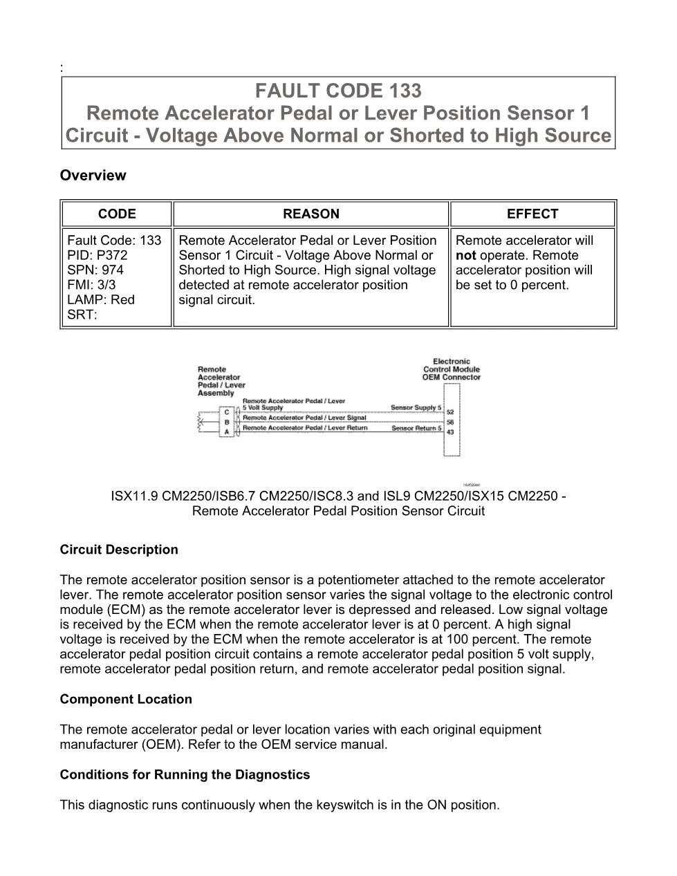
- Overview — Circuit Description and Component Location
- Fault Code 133 Summary (PID P372, SPN 974, FMI 3/3)
- Conditions for Running the Diagnostics
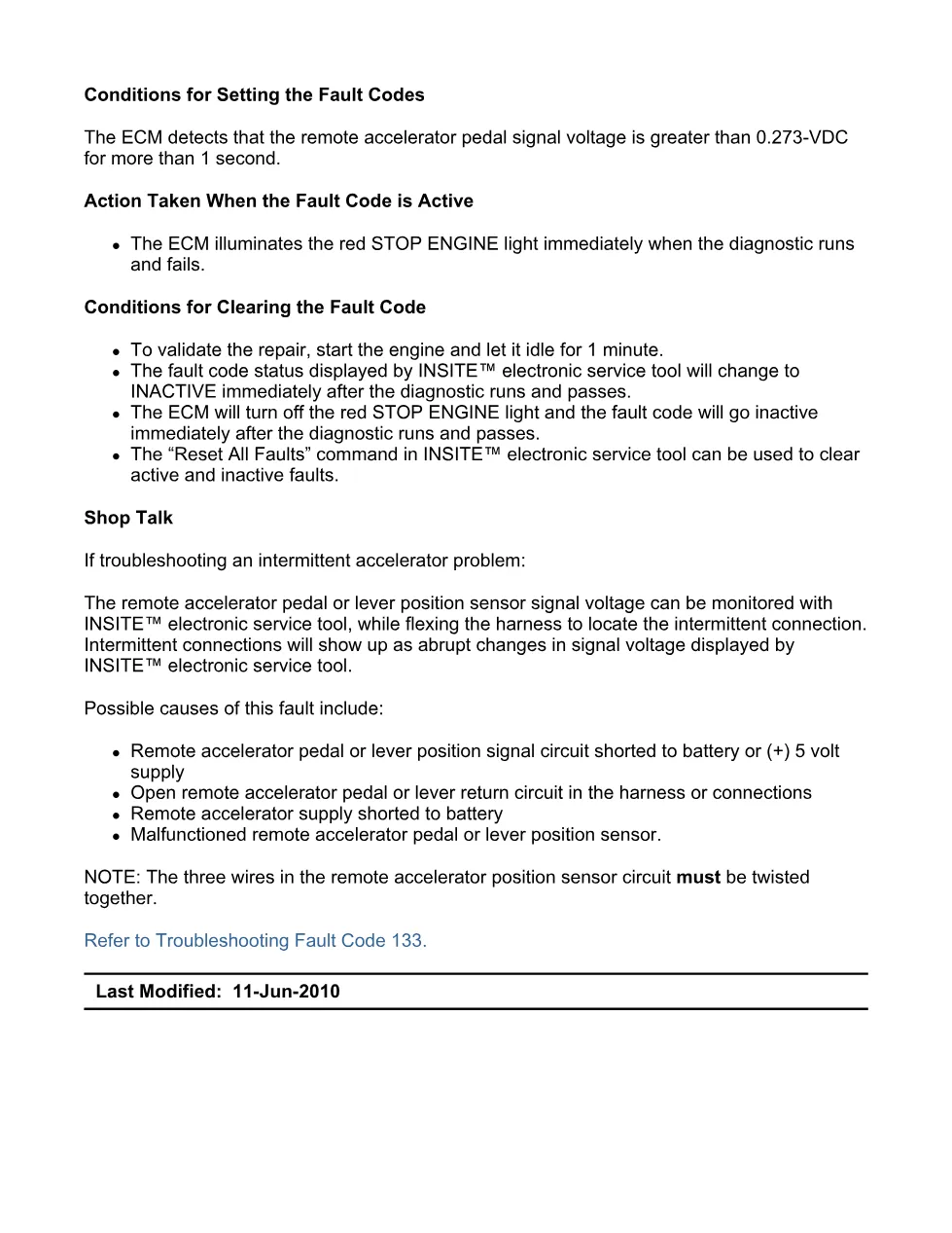
- Conditions for Setting the Fault Code (signal voltage greater than 0.273 VDC for more than 1 second)
- Action Taken When the Fault Code is Active — Red STOP ENGINE lamp
- Conditions for Clearing the Fault Code
- Shop Talk — Intermittent Troubleshooting and Possible Causes
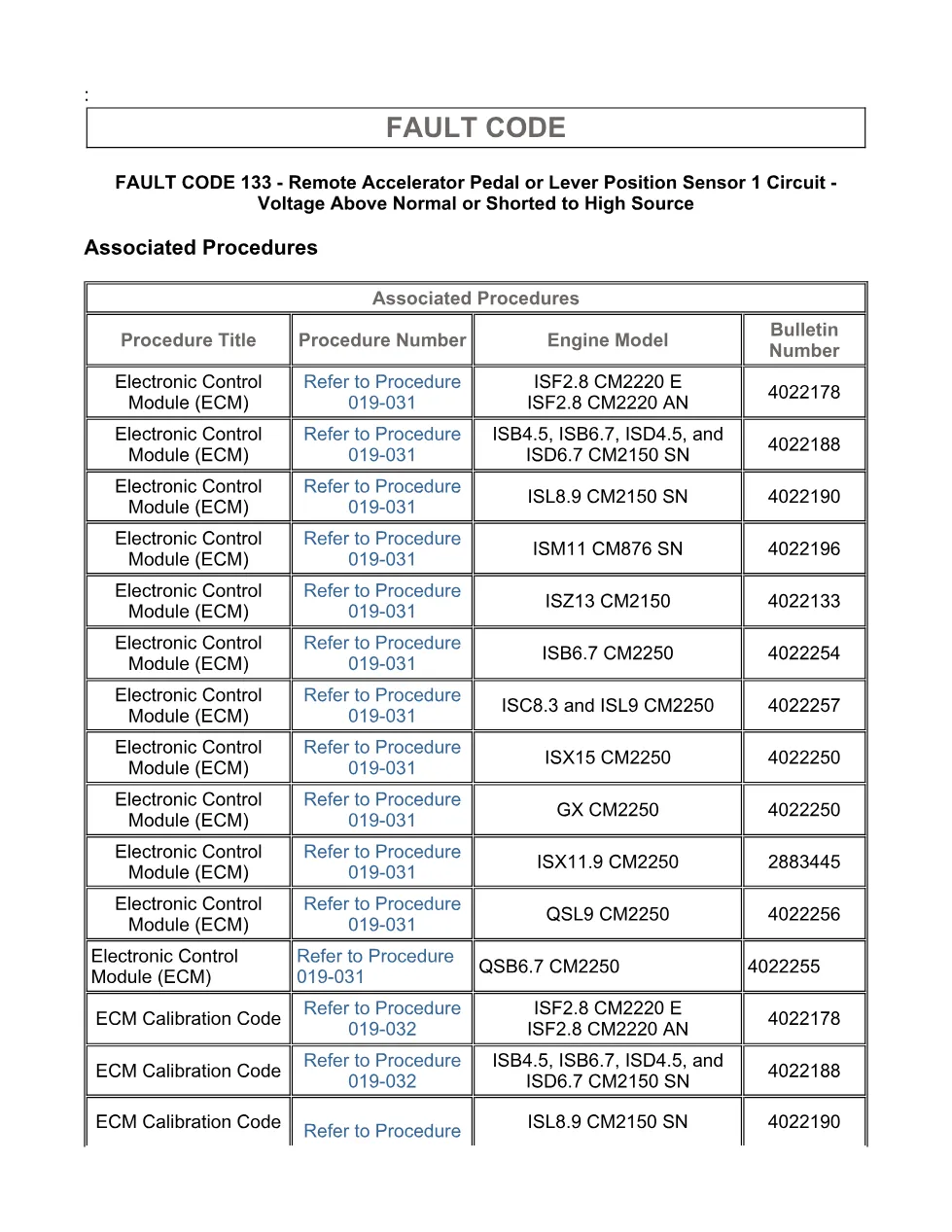
- Associated Procedures Table (Procedure 019-031, 019-032, 019-071, 019-359, 019-361, 019-362)
- Step 1 — Check Fault Codes (1A: Sensor Supply Fault Codes 1695/1696; 1B: Active Fault Code 133)
- Step 2 — Check Remote Accelerator Pedal Sensor Supply Voltage and Return Circuit (2A–2D)
- Step 3 — Check the ECM and OEM Harness (3A–3D: pin inspection, open circuit, pin-to-pin short)
- Step 4 — Check ECM Calibration and Clear Fault Codes (4A–4B)
Applicable truck models
This procedure applies to any vehicle or equipment using Cummins CM2250-series electronic control modules, including the ISB6.7 CM2250 (2010–2012), ISX11.9 CM2250, ISC8.3 and ISL9 CM2250, ISX15 CM2250, QSB6.7 CM2250, QSL9 CM2250, and GX CM2250 engines. The remote accelerator pedal or lever location varies by OEM installation; consult the OEM service manual for component location. Voltage specifications require 4.75 to 5.25 VDC at the sensor supply, and resistance readings below 10 ohms or above 100k ohms determine harness integrity. INSITE™ electronic service tool is required for fault code reading, signal monitoring, and calibration updates. For official engine documentation visit Cummins official website.
Who needs this Fault Code 133 DTCs manual
Diesel mechanics, fleet maintenance technicians, and workshop owners diagnosing a red STOP ENGINE lamp caused by high signal voltage on the remote accelerator circuit will need this guide. It is essential for anyone performing harness continuity checks, sensor replacement, or ECM calibration verification on CM2250-equipped Cummins engines.
The full PDF is available in the DiagTechPro manuals library, free account required to download.
Related manuals library
Sản phẩm liên quan cho hãng này
Cùng brand theo taxonomy hiện có trong catalog WooCommerce.

Cummins Calterm Version 5.16 – Advanced ECM Control and Precision Tuning for Cummins Engines

Cummins INSITE 9.3 – The Essential Diagnostic Tool for Cummins Engines

Cummins InCal CE – The Calibration and Configuration Tool for Cummins Engines


