
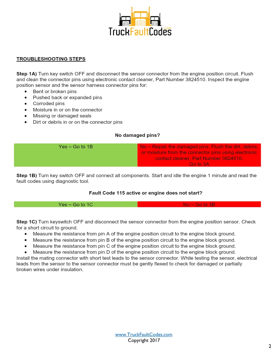
The Cummins M11 115 sheet documents the engine position sensor circuit (PID P190, SPN 190, FMI 2) on Cummins CELECT engines built from 1990 to 1994. This 7-page reference drives a technician through the circuit description, engine position sensor location, and the pin-by-pin checks needed to turn the red lamp off.
Cummins M11 115: Official document details
| Brand | Cummins |
| Model coverage | M11 and N14 CELECT (1990-94) |
| System / Group | Engine position sensor (EPS) circuit |
| Fault code identifier | Code 115 · PID P190 · SPN 190 · FMI 2 · SRT 00-081 |
| Warning lamp | Red |
| Pages | 7 |
| File size | 0.4 MB |
| Format | |
| Language | English |
Document table of contents
- Circuit description
- Component location on M11 and N14
- Shop talk on cranking rpm
- Sensor short-to-ground and coil checks
- Pinout and continuity checks
- Troubleshooting Steps 1A to 3B
- Clearing inactive fault codes
Applicable truck models
This procedure applies to Cummins M11 CELECT engines built from 1990 to 1994 and shares the engine position sensor logic used on N14 CELECT engines of the same era. It is a fault-code troubleshooting sheet from the CELECT diagnostic set (SRT 00-081), not a full engine manual, so confirm exact wiring and part numbers against factory data on the official Cummins website before replacing any component.
Cummins M11 115 diagnostic steps
Clean the sensor connector with electronic contact cleaner Part Number 3824510, then check each engine position sensor pin for a short to ground above 10M ohms. Remove and inspect the sensor for metal debris or camshaft damage, and measure the coils — pin A to D and B to C read 1000 to 2000 ohms, while A to B reads above 10M ohms. Verify the harness pinout (red to D-14, black to A-11, white to B-15, green to C-1) and check pins 1, 11, 14, and 15 for shorts, monitoring cranking rpm on the diagnostic tool.
Who needs this Cummins M11 115 manual
Technicians facing a no-start with no rpm signal use this FMI 2 sheet to confirm the engine position sensor, its coils, and harness pinout against factory values before condemning the ECM.
The full PDF is available in the DiagTechPro manuals library; a free account is required to download.
Applies to these truck models
This is the manufacturer document shared across 2 model families. It applies to:
- Cummins DTCs
- Cummins M11 CELECT (1990-94)
Related manuals library


Sản phẩm liên quan cho hãng này
Cùng brand theo taxonomy hiện có trong catalog WooCommerce.
Cummins INSITE 10.2 – Latest Diagnostic Software for Cummins Engines
Cummins Calterm Version 5.16 – Advanced ECM Control and Precision Tuning for Cummins Engines
Cummins InCal CE – The Calibration and Configuration Tool for Cummins Engines