
This Cummins 2321 fault code document is a 12-page diagnostic PDF for the engine crankshaft speed/position sensor circuit on CM2150 engines. It explains the code reason, operating effect, fault-setting logic, inspection points, road test steps, and clearing procedure for workshop use.
Official Cummins 2321 fault code document details
| Brand | Cummins |
|---|---|
| Model coverage | ISB, ISC, and ISL with CM2150; file group lists ISB6.7 CM2150 (2007-09) |
| System/Group | Engine Crankshaft Speed/Position Sensor Circuit / DTCs |
| Year/Revision | Unknown; Last Modified: 30-Aug-2010 and 20-Jul-2010 |
| Pages | 12 |
| File size | 0.2 MB |
| Format | |
| Language | English |
Document table of contents
- Overview
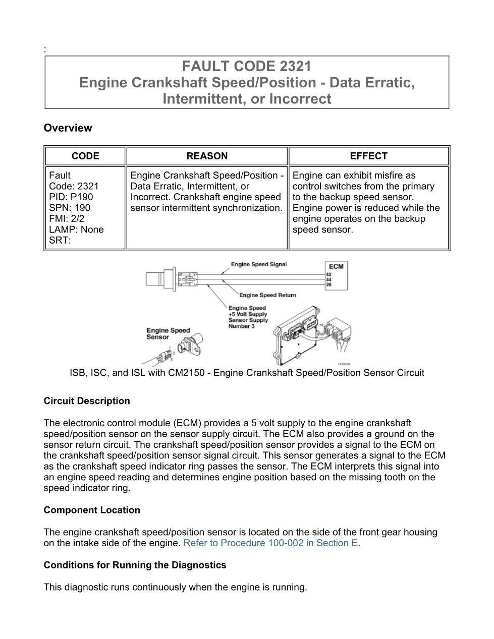
- Circuit Description
- Component Location
- Conditions for Running the Diagnostics
- FAULT CODE 2321
- Conditions for Setting the Fault Codes
- Action Taken When the Fault Code is Active
- Conditions for Clearing the Fault Code
- Shop Talk
- Associated Procedures
- Troubleshooting Steps
- Guided Step 1 – Check the fault codes.
- Guided Step 2 – Check the primary speed sensor circuit (crankshaft sensor).
- Guided Step 3 – Vehicle test.
- Guided Step 4 – Clear the fault codes.
Applicable truck models
This file applies to Cummins ISB, ISC, and ISL engines with CM2150 control, and the listing identifies ISB6.7 CM2150 (2007-09) DTC coverage. The procedure focuses on the primary speed sensor, also described as the engine crankshaft speed/position sensor, located on the side of the front gear housing on the intake side of the engine. See the manufacturer at Cummins official website.
Who needs this Cummins 2321 fault code manual
Mechanics, fleet technicians, and workshop owners need this Cummins 2321 fault code manual when an engine shows intermittent misfire, intermittent low power, or reduced power while the ECM uses the backup speed sensor. It is also useful when INSITE™ electronic service tool shows Fault Code 689 active or with high inactive counts, because the document directs the technician to the Fault Code 689 troubleshooting tree before continuing.
The diagnostic content describes how the ECM provides a 5 volt supply and sensor return, then interprets the crankshaft speed/position sensor signal from the speed indicator ring. The troubleshooting steps cover connector pin checks, harness insulation damage, moisture, corroded pins, bent or broken pins, pushed back or expanded pins, missing seals, damaged locking tabs, and intermittent shorts to the block or nearby components. Later steps include a road test, manual harness manipulation from the ECM connector toward the engine speed sensor connector, and inspection of air gap and target wheel condition.
The extract gives the sensor air gap limits as minimum 0.96 mm [0.038 in], maximum 2.25 mm [0.089 in], and maximum target runout 0.5 mm [0.02 in]. If the air gap is outside specification, the procedure says to replace or shim the sensor; if target runout is excessive, replace the target. The final section covers disabling the fault code by idling the engine for 1 minute, verifying inactive status with INSITE™, and clearing inactive fault codes after all components are connected.
Full PDF available in the DiagTechPro manuals library, free account required to download.
Related manuals library
Sản phẩm liên quan cho hãng này
Cùng brand theo taxonomy hiện có trong catalog WooCommerce.

Cummins Calterm Version 5.16 – Advanced ECM Control and Precision Tuning for Cummins Engines

Cummins INSITE 9.3 – The Essential Diagnostic Tool for Cummins Engines

Cummins InCal CE – The Calibration and Configuration Tool for Cummins Engines


