
This 227-page PDF is the Allison 5th generation IO input and output configurations reference, documenting every sensor input, solenoid output, and electronic interface used by fifth-generation Allison automatic transmissions. It serves as the primary wiring and signal-identification resource for technicians working on vehicles equipped with these transmission control systems.
Official Allison 5th generation IO document details
| Brand | Allison Transmission |
| Model coverage | 5th Generation Allison Automatic Transmissions |
| System / Group | Input and Output Configurations |
| Publication no. | Not specified in extract |
| Year / Revision | Unknown |
| Pages | 227 |
| File size | 66.6 MB |
| Format | |
| Language | English |
Document table of contents
- Introduction to 5th Generation Controls
- Transmission Control Module (TCM) Overview
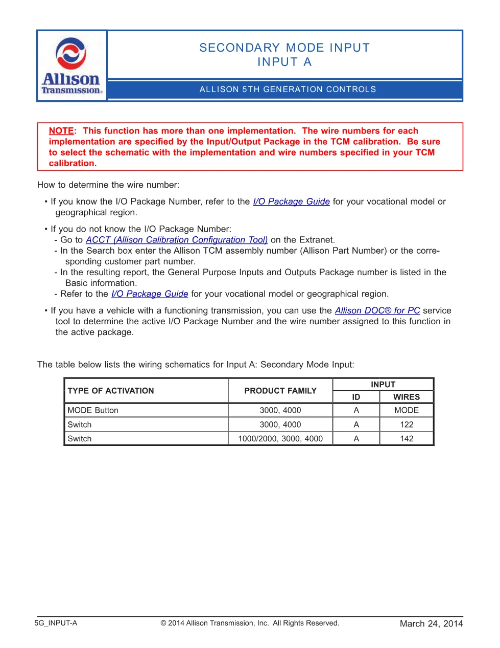
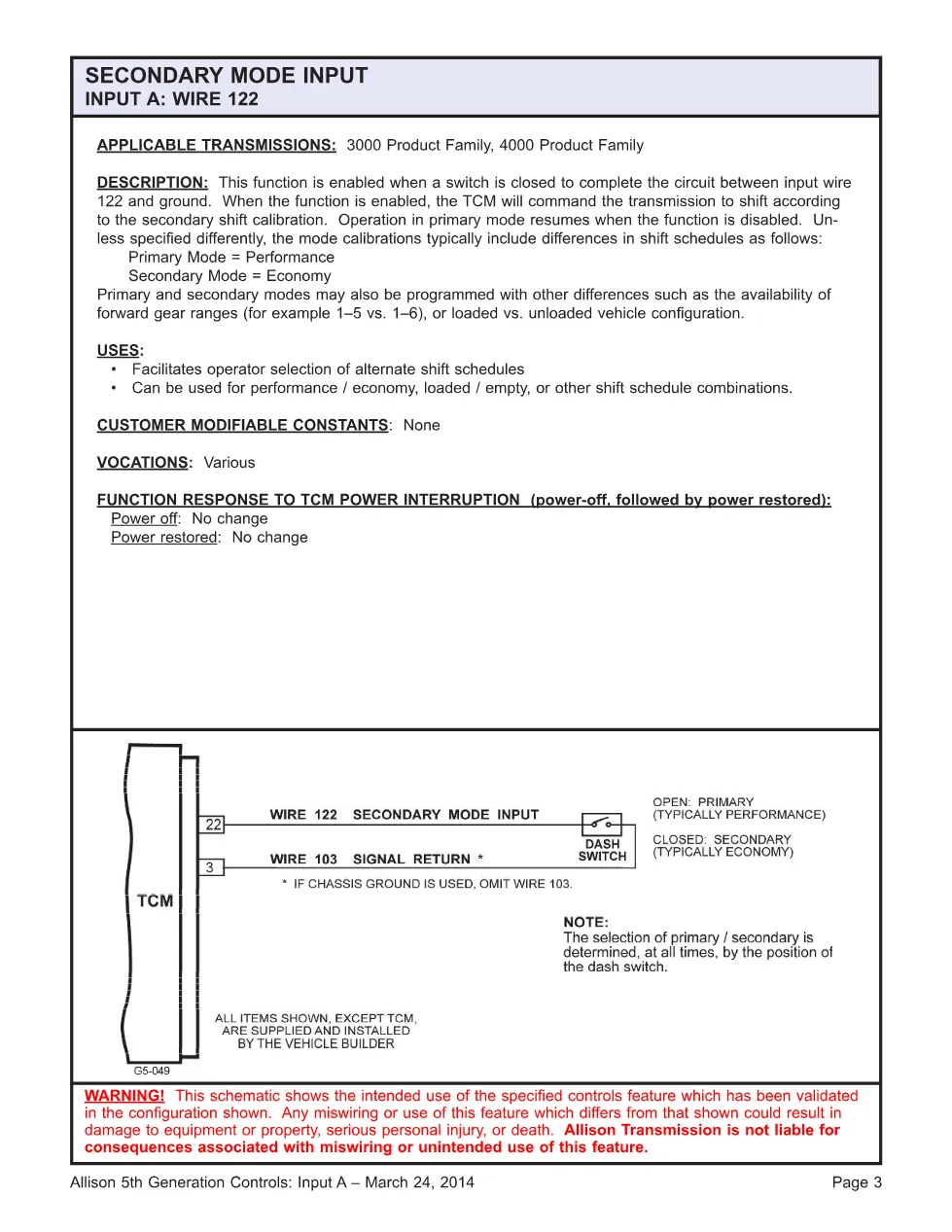
- Input Signal Descriptions — Speed Sensors, Temperature Sensors, Pressure Switches
- Output Signal Descriptions — Solenoid Commands, Indicator Lamp Drivers
- Wiring Harness Connector Pinouts
- CAN / J1939 Data Link Input and Output Messages
- Diagnostic Trouble Code Cross-Reference to I/O Circuits
- Calibration and Configuration Parameters
Applicable truck models
This manual applies to medium-duty and heavy-duty commercial vehicles fitted with Allison 5th generation electronically controlled automatic transmissions, including the 1000, 2000, 3000, and 4000 series where the Gen 5 TCM platform is installed. Common host vehicles include school buses, refuse trucks, utility trucks, and over-the-road vocational chassis from manufacturers such as Freightliner, International, Kenworth, and Peterbilt. For official transmission specifications and current software releases, visit Allison Transmission’s official website.
Who needs this 5th generation IO manual
Fleet maintenance technicians, independent transmission rebuild shops, and mobile diagnostic specialists who troubleshoot shift-quality complaints, solenoid faults, or sensor-related DTCs on Gen 5 Allison units will find this reference essential. Workshop owners preparing for Allison DOC or Allison Hub diagnostics can use the I/O tables to verify expected voltage ranges and CAN message assignments before connecting a scan tool.
The full PDF is available in the DiagTechPro manuals library; a free account is required to download.
Related manuals library

Sản phẩm liên quan cho hãng này
Cùng brand theo taxonomy hiện có trong catalog WooCommerce.
ALLISON TCM REFLASH


