
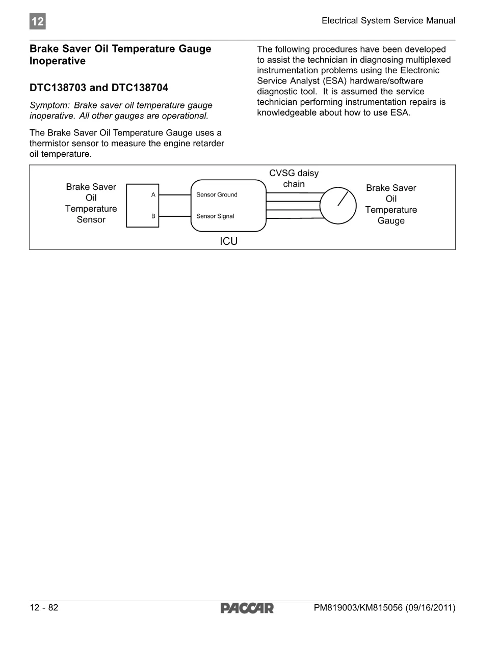
PACCAR’s brake saver temp sensor circuit procedure documents diagnostic trouble code DTC138703, logged when the CECU on a multiplexed Kenworth or Peterbilt detects an open in the brake saver oil temperature sensor circuit. Published under bulletin PM819003/KM815056 (09/16/2011) as part of the Electrical System Service Manual, the page pairs the brake saver temp sensor fault with its short-circuit counterpart, DTC138704, for complete gauge coverage. Because the Electronic Service Analyst tool shows the same CVSG data link wiring diagram for every gauge on the daisy chain, isolating a genuine brake saver temp sensor fault means following the sensor-specific pin numbers and resistance table given in the step-by-step procedure below.
Document details and specifications — brake saver temp
| Brand | PACCAR |
| Model coverage | Kenworth and Peterbilt trucks, 2011 and newer, CECU3 with Chassis Node |
| System/Group | DTCs / Cab (2011 & Newer) — Electrical System Service Manual |
| Publication no. | PM819003/KM815056 |
| Year/Revision | 09/16/2011 |
| Pages | 4 |
| File size | 0.1 MB |
| Format | |
| Language | English |
Table of contents
- Brake Saver Oil Temperature Gauge Inoperative
- DTC138703 and DTC138704
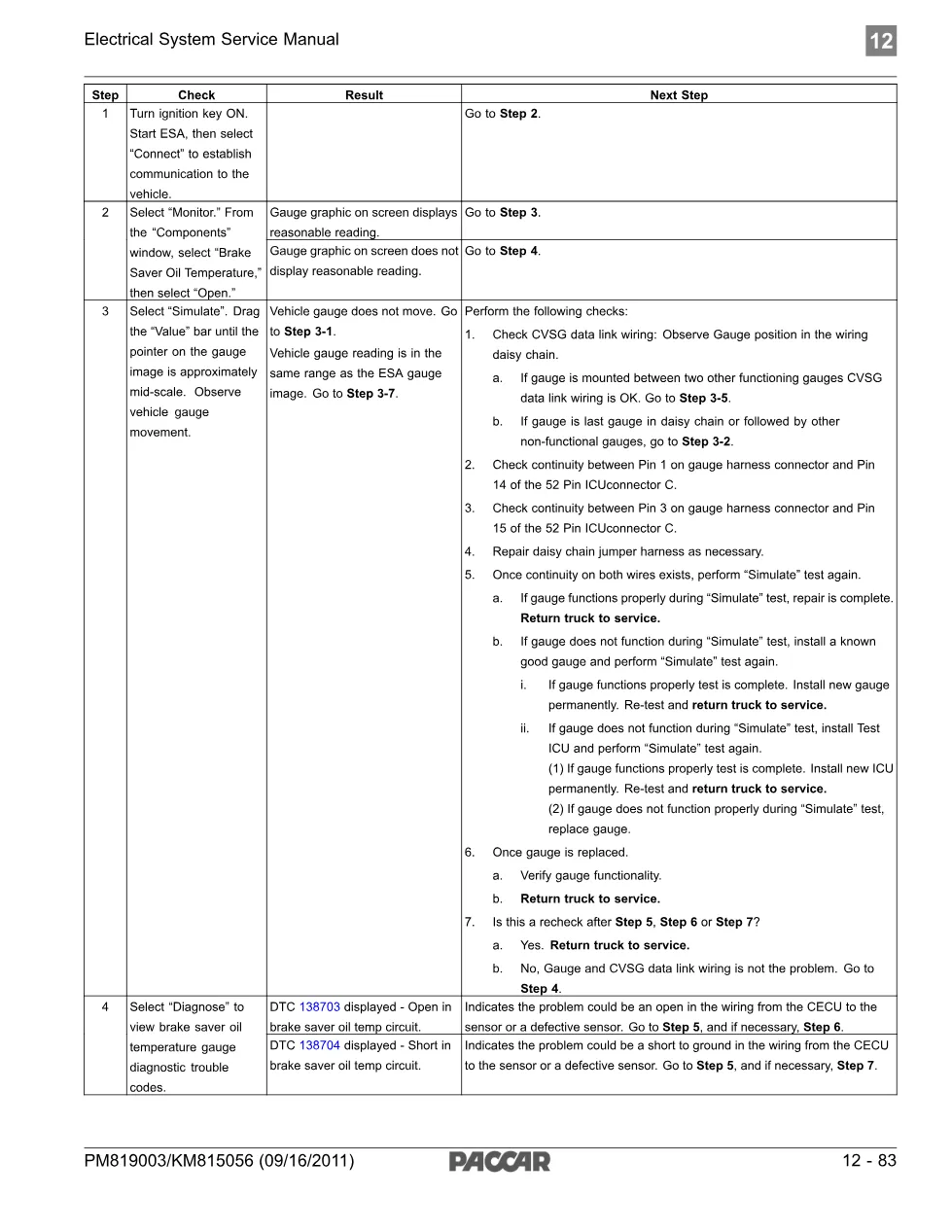
- Step 1-3: ESA Connect, Monitor, Simulate
- Step 4: Diagnose gauge DTCs (Open circuit path)
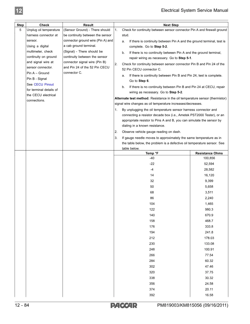
- Step 5: Sensor and CECU pin continuity checks
- Step 6: Confirm open-in-sensor vs. open-in-wiring
Applies to these models
This saver temp sensor diagnostic applies to PACCAR-built Kenworth and Peterbilt trucks with the CECU3 multiplexed electrical system and Chassis Node, model year 2011 and newer, where the brake saver oil temperature gauge reads inoperative while every other gauge on the cluster keeps working normally. See the PACCAR official site for chassis and engine platform coverage.
Who needs this saver temp sensor manual
Fleet technicians chasing a dead brake saver oil temperature gauge, or anyone who has already pulled DTC138703 on ESA, need this saver temp sensor walkthrough to confirm whether the fault sits in the thermistor sensor itself, the CVSG daisy-chain wiring, or the CECU connector before replacing parts.
The full PDF, including the full pin-by-pin continuity and resistance-table steps is available in the DiagTechPro manuals library; a free account is required to download.
Related manuals library
Sản phẩm liên quan cho hãng này
Cùng brand theo taxonomy hiện có trong catalog WooCommerce.


