

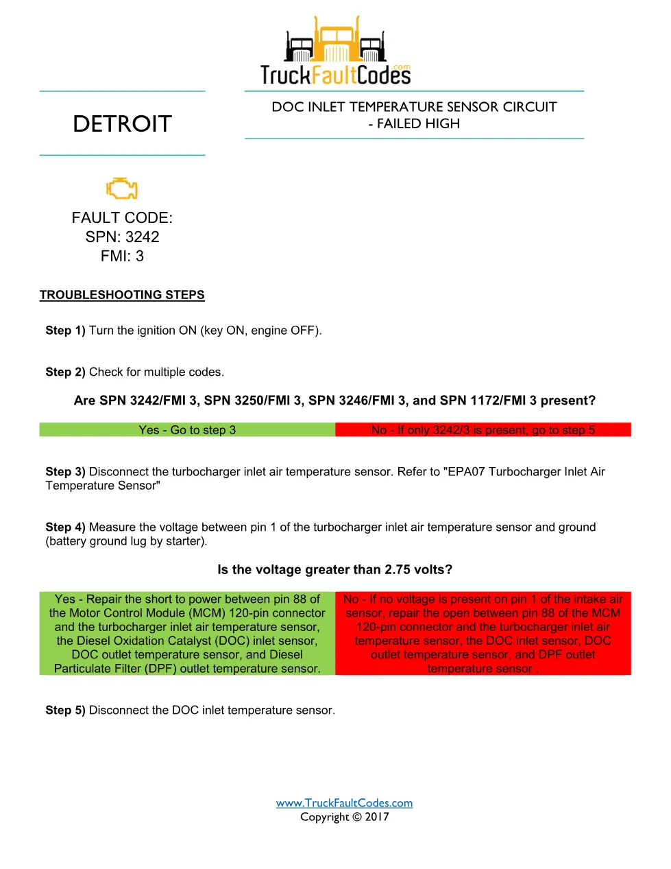
3242 FMI 3 EPA07 is the Detroit DD Series fault-code procedure for a diesel oxidation catalyst inlet temperature circuit failed-high fault. This 3-page diagnostic PDF documents the fault, its monitored circuit on the diesel oxidation catalyst (DOC) inlet temperature sensor, and the exact troubleshooting steps a technician follows to confirm and repair the failure.
Official document details
| Brand | Detroit |
| Model coverage | DD Series (EPA 2007-Current); Series 60 DDEC VI |
| System / Group | DD Series / DTCs |
| SPN (fault code) | 3242 |
| FMI (failure mode) | 3 |
| Emission family | EPA07 calibration |
| Source | Detroit Power Service Literature (Copyright © 2017) |
| Pages | 3 |
| File size | 0.26 MB |
| Format | |
| Language | English |
Document table of contents
- Fault code identification (fault 3242, failure mode 3)
- Troubleshooting steps
- Multiple-code check and turbocharger inlet air sensor
- DOC inlet sensor resistance and voltage checks
Applicable truck models
This procedure applies to Detroit DD13, DD15 and DD16 engines in the DD Series (EPA 2007-Current) range and the equivalent Series 60 (DDEC VI) platform, as fitted to Freightliner and Western Star trucks. Confirm the EPA07 emission family matches the truck before following the steps; full model and coverage data is published on the Detroit official website.
Who needs this 3242 FMI 3 EPA07 manual
Diesel technicians, fleet workshops and mobile mechanics diagnosing a DOC inlet temperature circuit failed-high code on EPA07 Detroit engines need this reference to test the circuit correctly with a diesel diagnostic tool instead of replacing parts by guesswork.
3242 FMI 3 EPA07 repair steps explained
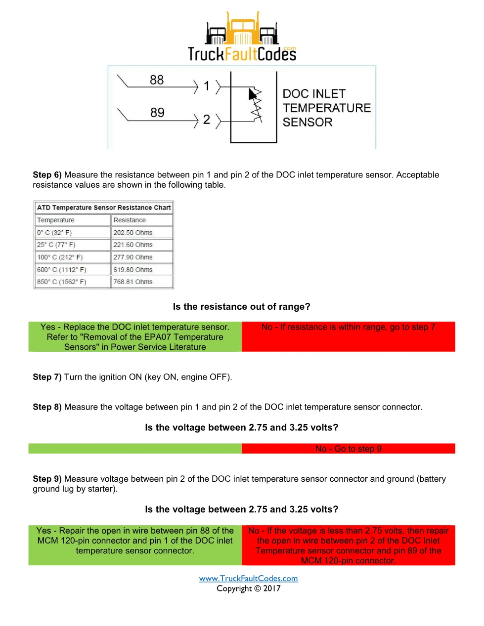
Because the EPA07 sensors share a supply, the procedure first checks whether related codes are present alongside SPN 3250/FMI 3, SPN 3246/FMI 3 and SPN 1172/FMI 3; if so, the turbocharger inlet air temperature sensor and pin 88 of the Motor Control Module (MCM) 120-pin connector are tested for a short to power or an open. The DOC inlet temperature sensor resistance is measured between pins 1 and 2 against the published table, and the connector voltage should read between 2.75 and 3.25 volts. Out-of-range sensors are replaced per Detroit Power Service Literature.
The full PDF is available in the DiagTechPro manuals library; a free account is required to download it.
Related manuals library

Sản phẩm liên quan cho hãng này
Cùng brand theo taxonomy hiện có trong catalog WooCommerce.

Detroit Diesel Reports 6.3
Detroit Reprogramming Station (DDRS) 7.11

DDDL Backdoor Password: A Comprehensive Guide